12 / 66 P/N 1070341 (ML) • REV F • ISS 16APR18
EN: Installation Sheet
Description
This manual provides information for the following access
control data gathering panel (DGP): ATS1250, ATS1260,
ATS1251, ATS1252, ATS1253 and ATS1254. When referring
to the four-door/four-lift DGP, this can be read as any variant of
the ATS125x/ATS1260, unless specifically stated otherwise.
Table 1: List of existing four-door / four-lift DGP variants
* In case of 24 V variant always use 2 batteries in series.
ATS125x/ATS1260 four-door/four-lift DGP
overview
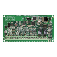
Figure 1: ATS125x
(1) DIP switches (see “DIP switch settings” on page 15).
(2) RAM or IUM (optional).
(3) EPROM (factory fitted).
(4) KILL jumper: Factory default ATS125x when shorted.
(5) Battery fuse F1.
(6) Auxiliary power fuse F2.
(7) Databus 1 fuse F3.
(8) Databus 2 fuse F4.
(9) Lock power 1 fuse F5.
(10) Lock power 2 fuse F6.
(11) Siren / switch fuse F7
(12) L1–L4 LED
(13) TERM 1. Use this link to terminate the system databus.
(14) TERM 2. Use this link to terminate the local databus, connection
1 on terminal CON9.
(15) TERM 3. Use this link to terminate the local databus, connection
2 on terminal CON10.
(16) CON14 Input expander connector
(17) CON15 Output expander connecter
(18) Mains terminal
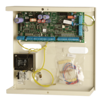
Figure 2: ATS1250/ATS1260
(1) Battery 1 fuse F1.
(2) Battery 2 fuse F2.
(3) Aux. power fuse F3.
(4) EXT readers fuse F4.
(5) AUX switchable output fuse F5.
(6) Local databus fuse F6.
(7) KILL jumper. Factory default ATS1250/1260 when shorted.
(8) EPROM (factory fitted).
(9) FLASH (factory fitted).
(10) RAM or IUM (optional).
(11) TERM 2. Use this link to terminate the system databus.
(12) DIP switches (see “DIP switch settings” on page 15).
(13) Clockout – connection to output cards. +12 V DC supply and
open collector or data outputs; for connection to output
controllers.
(14) TERM 1. Use this link to terminate the local databus.
(15) +12 V DC link for ATS1810/ATS1811/ATS1820.
(16) Mains terminal
Connections
Table 2: ATS125x connections
System earth (see “Earthing” on page
14).
2 x 12 V batteries, 7.2 Ah (24 V version)*
1 x 12 V battery, 7.2 Ah (12 V version)
System databus and panel tamper wiring
(see “ATS system databus connection” on
page 14 for details).
Local databus to connect RASs and
DGPs (see “ATS125x/1260 local databus
and earth connection” on page 14 for
details).
Local databus to connect RASs and
DGPs (see “ATS125x/1260 local databus
and earth connection” on page 14 for
details).
* In case of 24 VDC variant always use two batteries in series.
** External siren output is a supervised output. Typical EOL resistor
is 1 k.
Table 3: ATS1250/1260 connections
System earth (see “Earthing” on
page 14).
2 x 12 V batteries, 7.2 Ah
System databus and panel
tamper wiring (see “ATS system
databus connection” on page 14
for details).