14 / 66 P/N 1070341 (ML) • REV F • ISS 16APR18
• Avoid loops of wire inside the control panel cabinet and
route cables so that they do not lie on top or underneath
the printed circuit board. The use of cable ties is
recommended and improves neatness of the wiring within
the box.
• The battery used with this unit, must be made of materials
of suitable flammability class (HB or better).
• Any circuit connected either directly to the on board relay’s
contact or to external relay’s contact through the on board
electronic output, must be of SELV (safety extra-low
voltage) operating circuit.
- Mains switching relay must not be fitted inside the control
panel cabinet
- Always place a suppression diode (e.g. a 1N4001)
across the relay coil
- Use only relay with good insulation between the contacts
and the coil.
• The minimum clearance between equipment closures is
50 mm (between equipment vents).
• Only use units in a clean environment and not in humid
air. See “Specifications” on page 18 for more details on
the environment.
Cabling
System databus preferred wiring
The “TERM” link is on the first and last devices on the system
databus. In a “star”-wiring configuration, the “TERM” link is only
fitted on the devices at the ends of the two longest system
databus cable runs.
Figure 4
(1) GND link (do not fit).
(2) Earth lug to connect shield.
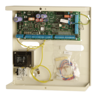
(3) ATS4000 control panel.
(4) ATS4000 TERM link fitted (first device on system databus).
(5) Preferred data cable type is WCAT 52 (2-pair twisted).
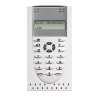
(6) ATS1110 LCD RAS (TERM switch not set to On).
(7) Separate 12 V power supply. Required if RAS is more than
100 m from the nearest panel or DGP. Connect “−” to “−” of the
databus.
(8) ATS125x/1260 TERM link fitted (last device on system databus).
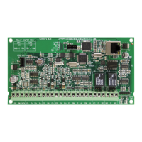
(9) ATS125x/1260 DGP.
Note: The local databus (not shown) has the same
requirements. The local databus is connected to CON9/CON10
of ATS125x, or J22 of ATS1250/1260.
See “ATS system databus connection”, “ATS125x/1260 local
databus and earth connection”, and earthing details below.
Earthing
WARNING: Correct earthing procedure must be followed.
Earthing of one cabinet containing several devices
All devices designed for the system have earth connections via
metal studs to the metal housing. Take care that these metal
studs have a good connection to the housing (beware of paint).
The earth connections of each piece of equipment in the
system can be used to connect the shielding of shielded
cables.
If a device is placed in a plastic housing, the earth lug of this
device also has to be connected, except for devices, which are
not provided with an earth lug.
Earthing panels in a single building
In a single building several cabinets or devices are earthed.
A licensed contractor must check the safety earth of this
building.
Earthing panels in more than one building
If the wiring extends to separate buildings, use more than one
common earth system. Use the ATS1740 isolator/repeaters to
isolate the system databus. This protects the system against
variations in earth potential.
Shielding
The shielding of all shielded cables used in the system should
only be connected on one side to one common earthing point
in a building. If a shielded databus cable is routed via more
than one plastic device, the shielding from the in-coming and
out-going cable must be connected.
Figure 3
(1) Mains power with local earth
(2) Mains power connector
(3) System databus
(4) Earth lug
(5) Building 1
(6) Building 2
(7) Device in metal housing
(8) Device in plastic housing
(9) ATS control panel
ATS system databus connection
See Figure 6.
The system databus is used to connect DGPs (such as
ATS125x) and arming stations to the ATS control panel.
Remote devices can be up to 1.5 km from an ATS control
panel.
Each remote device is assigned an address and is polled in
sequence by the ATS control panel. Up to 12 four-door/four-lift
DGPs can be connected on the main ATS system databus.
Arming stations and DGPs must be connected via a 2-pair
twisted shielded data cable from the system databus
connection (WCAT 52 is recommended).
Connect the shield of the data cable to earth at the ATS control
panel. It should be left disconnected at the other end.
The four-door/four-lift DGPs have their own built-in power
supply and do not require power from the databus. Only the
D+, D− and 0 V connections are required between the ATS
control panel and a four-door/four-lift DGP.
ATS125x/1260 local databus and earth
connection
See Figure 10.
ATS125x/ATS1260 allows for 16 arming stations (LCD-RASs,
Smart Card readers) and 15 DGPs (4-lift DGP only) to be
connected to the local databus (CON9/CON10 on ATS125x, or
J22 on ATS1250/1260).