20 / 66 P/N 1070341 (ML) • REV F • ISS 16APR18
Table 15: ATS1250/1260 external terminals
Secondary AC
transformer connection
Battery connection
(each)
External siren (self-
excitingt)
Contacts door relays
(each)
+12 V power for door
relays (each)
+12 V power for card
readers (each)
+5 V power for card
readers (each)
Notes
• Maximum total current consumption for auxiliary power outputs
(++/−−) and external siren should not exceed 2 A.
• Maximum total current consumption should not exceed 3 A,
including battery load current.
Regulatory information
UTC Fire & Security Americas Corporation, Inc.
3211 Progress Drive, Lincolnton, NC, 28092,
USA
Authorized EU manufacturing representative:
UTC Fire & Security B.V.
Kelvinstraat 7, 6003 DH Weert, Netherlands
Product warnings
and disclaimers
THESE PRODUCTS ARE INTENDED FOR
SALE TO AND INSTALLATION BY QUALIFIED
PROFESSIONALS. UTC FIRE & SECURITY
CANNOT PROVIDE ANY ASSURANCE THAT
ANY PERSON OR ENTITY BUYING ITS
PRODUCTS, INCLUDING ANY “AUTHORIZED
DEALER” OR “AUTHORIZED RESELLER”, IS
PROPERLY TRAINED OR EXPERIENCED TO
CORRECTLY INSTALL FIRE AND SECURITY
RELATED PRODUCTS.
For more information on warranty disclaimers and
product safety information, please check
https://firesecurityproducts.com/policy/product-
warning/ or scan the QR code.
UTC Fire & Security hereby declares that this
device is in compliance with the applicable
requirements and provisions of the Directive
2014/30/EU and/or 2014/35/EU. For more
information see www.utcfireandsecurity.com or
www.interlogix.com.
2012/19/EU (WEEE directive): Products marked
with this symbol cannot be disposed of as
unsorted municipal waste in the European Union.
For proper recycling, return this product to your
local supplier upon the purchase of equivalent
new equipment, or dispose of it at designated
collection points. For more information see:
www.utcfssecurityproducts.eu/recycle/
Contact information
www.utcfireandsecurity.com or www.interlogix.com
For customer support, see www.utcfssecurityproducts.eu
FR: Instructions d’installation
Description
Ce manuel fournit les informations sur les DGP à 4 portes /
4 ascenseurs suivants: ATS1250, ATS1260, ATS1251,
ATS1252, ATS1253 et ATS1254. Le terme de DGP à 4 portes
/ 4 ascenseurs, se rapporte à n’importe quel modèle de
ATS125x/1260, à moins d’indication spécifique.
Tableau 1: Liste des modèles de contrôleurs à 4 portes
* Utiliser 2 batteries 12 V en série.
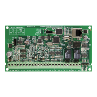
Présentation du DGP à 4 portes /
4 ascenseurs ATS125x/1260
Figure 1 : ATS125x
(1) Commutateurs DIP d’adressage (voir « Configuration des
commutateurs DIP » en page 24).
(2) RAM ou IUM (optionnel).
(3) EPROM (installée en usine).
(4) KILL — Retour aux paramètres usine de l'ATS125x.
(5) Fusible batterie F1.
(6) Fusible d'alimentation aux. F2.
(7) Fusible du bus de données 1, F3.
(8) Fusible du bus de données 1, F4.
(9) Fusible d’alimentation ventouse 1, F5.
(10) Fusible d’alimentation ventouse 2, F6.
(11) Fusible sirène, F7
(12) LEDs L1–L4
(13) TERM 1. Utilisez ce cavalier pour terminer le bus de données du
système.
(14) TERM 2. Utilisez ce cavalier pour terminer le bus de données
local, connexion 1 du bornier CON9.
(15) TERM 3. Utilisez ce cavalier pour terminer le bus de données
local, connexion 2 du bornier CON10.
(16) CON14 Connecteur d’extension d’entrées.
(17) CON15 Connecteur d’extension de sorties.
(18) Bornier secteur.