P/N 1070341 (ML) • REV F • ISS 16APR18 15 / 66
The ATS125x local databus consists of 2 electrically
independent loops. If there is a failure in one loop, the other
loop can still communicate with the remote devices. The
location of devices on the first or on the second loop has no
influence on the functionality, as both loops behave as one
databus.
Note: ATS1250/1260 has only one local databus loop.
Wire the door contacts and Request-to-Exit buttons associated
with each door to the ATS125x inputs.
Wire the floor monitoring and lift override zones to the 4-lift
DGP zones or zones on DGPs, which are connected to the
local databus not on the ATS system databus. There are spare
zones for other devices, such as PIRs.
Any zone used for DOTL (Door Open Too Long) cannot have
any wiring connected.
Each unit is assigned an address and is polled in sequence by
the ATS125x on each loop. Remote units can be located
anywhere up to 1.5 km from the ATS125x. Each loop must
have termination on both ends.
Table 5: ATS1190 wiring
Connection door contact and Request-to-Exit button
Figure 7
(1) Door contact
(2) Request-to-Exit button (push button)
Door lock connection
See Figure 8.
DIP switch settings
DIP switches 1 to 4 (DGP address) are used to identify this
DGP to the Advisor Master control panel, i.e. Assign the DGP
address. A four-door/four-lift DGP can only be addressed, as
DGPs 1 to 12. See Figure 9.
DIP switches 5 and 6 are used for zone expansion
configuration (ATS125x only).
Figure 5
(1) 8 onboard inputs (no expanders)
(2) 8 onboard inputs + 1xATS1202
(3) 8 onboard inputs + 2xATS1202
(4) 8 onboard inputs + 3xATS1202
DIP switches 7 and 8 are not used.
Zones, RASs and outputs
Numbering
All DGPs, zones, RASs and outputs are numbered according
to a set formula. This is used when determining the physical
numbers/locations of DGPs, outputs etc. during programming.
Table 6: Zones, RASs and outputs allocated per DGP
Zones
A four-door/four-lift DGP has a maximum of 16 zones available
(or 32 zones, if occupies 2 addresses – ATS125x only). These
zones follow the standard zone numbering.
For example: ATS125x 1 is DGP 1 and has 16 zones, which
the ATS control panel identifies as zones 17 to 32.
If all 32 zones are used, the next DGP address is not available.
For example: DGP 1: zones 17-48, DGP2 is not available,
DGP3: zones 49-64.
See “ATS125x/1260 default zone and relays settings” on page
16 for more details on default zone and unlock relay settings.
Note: The ATS125x four-door DGP has only 8 zones on
board. Another 24 zones can be connected with ATS1202
zone expanders.
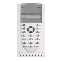
RASs
Card readers, keypads (ATS110x, ATS115x), and ATS1170
are polled as RASs. Polling allows the RAS to transfer data to
the ATS125x. RASs are connected to the ATS125x local
databus. Each RAS has a unique number in the system
depending on four-door DGP address and RAS address on
local databus. See Table 6 above for more details.
16 RASs can be connected to each ATS125x local databus.
The RAS addresses relate to specific doors on the ATS125x,
and to the reader location if readers are mounted on both sides
of the same door.
Table 7: RAS address and reader function
Outputs
The four-door/four-lift DGP has one output available as
a switched power output (external siren output). There are also
four on-board unlock relays available, one for every door.
A four-door/four-lift DGP can address 48 outputs in total using
macro logic.
Output controllers are used to expand the number of outputs
on a DGP. Each output controller expands the outputs by
eight. Output and zone numbers are always the same as the