18 / 66 P/N 1070341 (ML) • REV F • ISS 16APR18
Rx (ATS125x)
Rx1 (ATS1250/1260)
The yellow LED flashes to indicate remote
devices reply to polling.
If the LED does not flash, the RASs are not
programmed to be polled, addressed
incorrectly or the bus is faulty.
• Check that RASs are powered correctly.
• Check wiring RAS data bus connections.
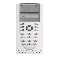
• Check that the RASs
(readers/interfaces) are polled
(ATS125x/1260 menu 1.4 “Poll RAS”).
• Check that RASs are addressed
correctly.
Specifications
Default: 4.7 kΩ, 2 %, 0.25 W
(Other: 10 kΩ, 2 %, 0.25 W; 2.2 kΩ,
2%, 0.25 W)
Mains power specifications
230 V~ 10%, 50 Hz 10%, 129 VA
max.
Current consumption at 230 V~
Main board supply voltage (J17)
Power supply specifications
ATS1251, ATS1253,
ATS1250/1260
4.0 A max. at 13.8 0.2 V
1.6 A max. at 27.6 V
and 1.1 A max. at 13.8 V
3.0 A max. at 13.8 0.2 V
13.8 0.2 V, 2 A max.
Note: Maximum permanent current
to power devices external to the
control equipment in the absence of
alarm conditions.
ATS1251, ATS1253,
ATS1250/1260
1.6 A max. at 27.6 V and
1 A max. at 13.8 V
Notes
• Remaining current means all available current that can be used
for the following: Auxiliary power (incl. switched), Battery charge,
Lock power and Local comms power. You can distribute the total
available current over the terminals as long as the maximum
remaining current and fuse rating for each output is respected.
• The needed battery current is dependant on the approval grade.
See “Auxiliary current and battery capacity” below for determining
which current should be reserved for charging the battery. Note
that Auxiliary power, Lock power and Local comms power is
limited by the battery current.
• For the 12 V variant 3900 mA can be distributed. Higher current
value drives the power supply into current limit.
• For the 24 V variant 1600 mA can be distributed over
27.6 V contacts (Locks and Battery) and 1000 mA can be
distributed over the 13.8 V contacts (Auxiliary power incl.
Switched and the Local Comms).
ATS125x Fuses
• F1 (Battery 1): 5 A, Fast 20x5
• F2 (Auxiliary power): 1 A, Fast 20x5
• F3 (Local databus 1): 800 mA, Fast 20x5
• F4 (Local databus 2): 800 mA, Fast 20x5
• F5 (Lock power 1): 2 A, Fast 20x5
• F6 (Lock power 2): 2 A, Fast 20x5
• F7 (Switched power): 1A, Fast 20x5
• Mains (Mains fuse): 800 mA, Slow 20x5
Note: Mains fuse is part of the mains terminal block.
ATS1250/1260 Fuses
• F1 (Battery 1): 5 A, Fast 20x5
• F2 (Battery 2): 5 A, Fast 20x5
• F3 (Auxiliary power and siren): 2 A, Fast 20x5
• F4 (Ext. reader power): 2 A, Fast 20x5
• F5 (Auxiliary switch output): 1 A, Fast 20x5
• F6 (Local databus): 1 A, Fast 20x5
• Mains (Mains fuse): 2 A, Fast 20x5
Note: Mains fuse is part of the mains terminal block.
WARNING: Before removing the mains fuse, the mains power
must be disconnected! See “Mains power connection” on page
13.
Auxiliary current and battery capacity
Note: This is only a reference to approval requirements.
Please contact your local sales office for more information
about valid certification.

 Loading...


