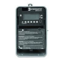
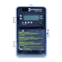
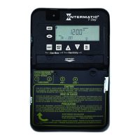
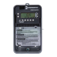
Latch location
Tilt top forward
Installation
Follow these instructions to install the time switch.
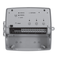
1. Open the time switch enclosure door.
2. Remove and retain the screw that secures the plastic insulator.
3. Lift the left side of the plastic insulator and pivot away to expose the terminal strip.
4. Press the latch at the top of the enclosure and pull out the mechanism from the
enclosure.
5. Choose and remove the selected knockout(s) from the enclosure.
NOTE: There are ve 1/2 inch to 3/4 inch combination knockouts available. There are
two on the bottom of the enclosure, one on each side, and one on the rear. If a 3/4
inch knockout is needed, remove the 1/2 inch knockout rst, then the 3/4 knockout.
6. Place the enclosure in the desired location providing space for the enclosure door to
swing open fully.
7. Securely mount enclosure using provided mounting holes.
8. Use appropriately rated ttings for the installation.
9. Snap the mechanism back into the enclosure.
10. Strip 1/2 inch off the supply and load wires. Use AWG #14 - #8 copper conductors
rated at least 105ºC. Torque to 15.6 lbf-in.
11. Connect the wires to the proper terminals on the time switch and tighten the screws
rmly (See wiring diagrams).
12. Connect ground wire to grounding terminal at the bottom of metal enclosures.
13. Return the insulator to its original position and replace the screw.
14. Close enclosure door.
15. Apply power to the time switch.
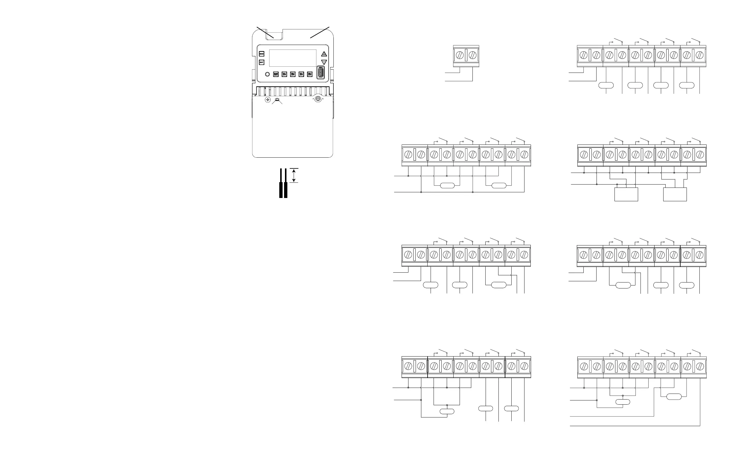
Wiring Diagrams
1/2 inch
LOAD 4LOAD 3LOAD 2
LOAD 1
L1
L2/N
N
L3 L4
N N
L6L5
N
OUTPUT CONFIGURATION: IND - CIRCUIT 1 AND 2
OUTPUT CONFIGURATION: IND - CIRCUIT 3 AND 4
CIRCUIT 1 CIRCUIT 2 CIRCUIT 3 CIRCUIT 4
POWER
NO-4
COM4COM3
NO-3
COM2
NO-2
COM1
NO-1
AC IN
OUTPUT CONFIGURATION: SIM - CIRCUIT 1 AND 2
OUTPUT CONFIGURATION: SIM - CIRCUIT 3 AND 4
L1
L2
CIRCUIT 1 CIRCUIT 2 CIRCUIT 3 CIRCUIT 4
TIMER
POWER
AC IN
NO-1
COM1
NO-2
COM2
NO-3
COM3
NO-4
COM4
LOAD 1
LOAD 2
TIMER CONFIGURATION FOR TWO 208/240 VAC DPST
L1
L2/N
CIRCUIT 4CIRCUIT 3CIRCUIT 2CIRCUIT 1
TIMER
POWER
OUTPUT CONFIGURATION:PUL - CIRCUIT 1 AND 2 (BELL RINGING)
OUTPUT CONFIGURATION: SIM - CIRCUIT 3 AND 4 (208/240 VAC LOAD)
TIMER CONFIGURATION FOR COMBINATION MODE
240VAC
LOAD1
COM4
NO-4
COM3
NO-3
COM2
NO-2
COM1
NO-1
AC IN
4 - INDIVIDUAL 120/277 VAC LOADS
AC IN
L2/N
L1
TIMER POWER
POWER TO TIMER
120/208/240/277 VAC
(AUTO VOLTAGE, NO JUMPERS REQUIRED)
LOAD 2
TIMER CONFIGURATION FOR TWO CONTACTOR CONTROLS
COM4
NO-4
COM3
NO-3
COM2
NO-2
COM1
NO-1
AC IN
TIMER
POWER
CIRCUIT 4CIRCUIT 3CIRCUIT 2CIRCUIT 1
L2/N
L1
OUTPUT CONFIGURATION: PUL - CIRCUIT 1 AND 2
OUTPUT CONFIGURATION: PUL - CIRCUIT 3 AND 4
OPEN
CLOSE
COM
COM
CLOSE
OPEN
TIMER CONFIGURATION FOR COMBINATION MODE
LOAD 3
LOAD 2
LOAD 1
L1
L2/N
OUTPUT CONFIGURATION: SIM - CIRCUIT 1 AND 2 (208/240 VAC LOAD)
OUTPUT CONFIGURATION: IND - CIRCUIT 3 AND 4 (120/277 VAC LOAD)
CIRCUIT 1 CIRCUIT 2 CIRCUIT 3 CIRCUIT 4
TIMER
POWER
NO-4
COM4COM3
NO-3
COM2
NO-2
COM1
NO-1
AC IN
L3 L5
N
L6
N
L7
AC IN
NO-1
COM1
NO-2
COM2
NO-3
COM3 COM4
NO-4
TIMER
POWER
CIRCUIT 4CIRCUIT 3CIRCUIT 2CIRCUIT 1
OUTPUT CONFIGURATION: IND - CIRCUIT 1 AND 2 (120/277 VAC LOAD)
OUTPUT CONFIGURATION: SIM - CIRCUIT 3 AND 4 (208/240 VAC LOAD)
N
L4L3
N
L2/N
L1
LOAD 1
LOAD 2
LOAD 3
L5 L6
TIMER CONFIGURATION FOR COMBINATION MODE
TIMER CONFIGURATION FOR COMBINATION MODE
OUTPUT CONFIGURATION: PUL - CIRCUIT 1 AND 2 (BELL RINGING)
OUTPUT CONFIGURATION: IND - CIRCUIT 3 AND 4
AC IN
NO-1
COM1
NO-2
COM2
NO-3
COM3
NO-4
COM4
LOAD1
LOAD2 LOAD3
TIMER
POWER
CIRCUIT 1 CIRCUIT 2 CIRCUIT 3 CIRCUIT 4
L2/N
L1
N
L3
N
L4

 Loading...