ET90000 Series Electronic Timer
5
2. MOUNT ENCLOSURE
1. Place the enclosure in the desired location and mark
the location of at least two of the keyhole openings
in the mounting bracket.
2. Drill holes.
3. Install anchors in wall, if needed.
4. Install screws at the keyhole locations.
5. Hang the enclosure on the screws.
6. Mark the location of at least two of the round holes
in the bottom bracket.
7. Remove the enclosure from the top screws and drill
holes for the bottom screws.
8. Install anchors in wall, if needed.
9. Select knockouts you would like to use. Remove the
inner 1/2 or 3/4-inch knockout by inserting a athead
screwdriver in the slot and carefully punch the
knockout loose. Remove slug. If a larger knockout
is required, remove the outer ring with pliers after
removing the inner knockout. Smooth edge if
necessary.
10. Place the enclosure on the wall using the keyholes
in the top mounting bracket.
11. Install the remaining screws through the bottom
bracket and tighten.
12. Tighten the screws through the top mounting bracket.
13. Close enclosure door before operating.
CONNECT TO POWER
A 120 to 277 VAC power source supplies electricity to the
ET90000-series electronic timer, normally run through
conduit. To connect the power wires to the unit, follow
this procedure:
1. Secure conduit connectors to conduit before
connecting the hubs to the enclosure. After inserting
connectors into enclosure, carefully tighten hub lock
nut. Do not over-torque.
2. Insert the black power wire into the power board
(marked “L1” or “AC”) and secure with a athead
screwdriver.
3. Insert the white neutral wire into the power board
(marked “L2/N” or “IN”) and secure with a athead
screwdriver.
IMPORTANT: Color of wires may vary.
4. 1 and 2 circuit system: Attach the green ground
wire to the green hex head screw at the bottom of
the enclosure and secure with a athead screwdriver.
4, 8, 12, 16 circuit system: Connect the input
power wires to the terminals at the top left corner
of the device. Connect the ground wire to the green
hex head screw at the lower left of the device (see
Figure1).
5. Close enclosure door.
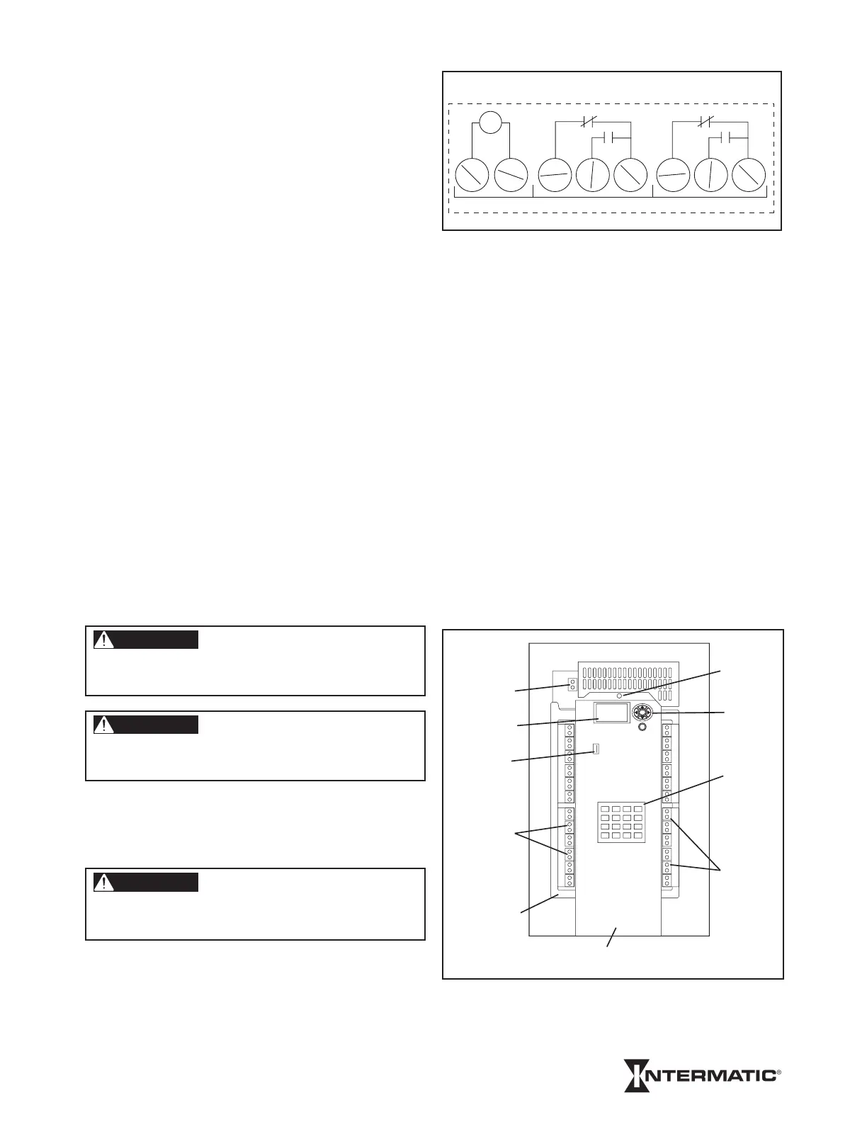
Figure 1: ET90000-Series Unit
(4, 8, 12, 16 circuit model)
WARNING
To avoid fire, shock, or death, turn off power at circuit breaker
and test that power is off before wiring.
WARNING
Make sure there is no wire insulation under the clamping plate
and firmly tighten the terminal screws.
CAUTION
Wire in accordance with national and local electrical and
safety codes.
NO-2NC-2NO-1NC-1
INAC
T
COM1 COM2
ET90215 2-CIRCUIT TERMINALS
TIMER
ELECTRICAL
POWER
TERMINALS
SCREEN
USB PORT
WIRING
TERMINALS
GROUNDING
CONNECTION
DOOR
SCREW
KEYPAD
ON/OFF
SWITCHES
WIRING
TERMINALS
CENTER KNOCKOUTS RESERVED FOR
LOW VOLTAGE WIRING
ESC
ENTER
Model_TEMP