EasyManua.ls Logo

Intermatic FF5M User Manual

Intermatic FF5M
6 pages
To Next Page IconTo Next Page
Page #1 background imageLoading...
Page #1 background image
~TERMATIC®
SPRING
WOUND
INTERVAL
TIMER
INSTALLATION
INSTRUCTIONS:
This
spring
wound
timer
is as easy to
install
as a
light
switch
in
a standard
2-1/2
inch
deep
vertically
installed
junction
box in
place
of
(or
to
replace) a standard single
pole,
3-way
or double
pole
single
throw
(depending on
timer
model)
wall
switch.
This
spring
wound
timer
will
automatically
turn
off
lights, fans,
air
conditioners
and
other
loads
after a preset
timing
period.
CAUTION:
This
timer
should
not
be
used
in
precision
timing
applications
where
inaccurate
timing
could
have
dangerous
consequences
(i.e.
sun
lamps,
sauna,
etcetera).
INSTALLATION:
Depending on
the
type
of
spring
wound
timer
you have, you
may need
to
supply a standard single or
multi-gang
wall
switch
plate
with
either
a toggie opening
or
a
decorator
type opening.
If
your
timer
is supplied
with
a
metal
time
dial
wall
switch
plate
(models
with
FF
prefix), see
illustration
"A".
If
your
timer
is
supplied
with
a
small
ivory,
white
or
other
colored
plastic
time
dial
plate
(models
with
FD
prefix), you
will
need
to
supply a
standard toggle or decorator design
wall
switch
plate
and see
illustration
"81"
or
"82".
1. Be sure
to
turn
off
electrical
power
at breaker
or
fuse
panel
for
safety
during
installation.
2.
Remove
wall
plate
and disconnect
switch
from
vertically
installed
junction
box.
3.
Strip
end
of
wires
1/2
inch long
as per
strip
gauge on
back
of
timer.
WIRE
STRIP
GAUGE
Question and Answer IconNeed help?

Do you have a question about the Intermatic FF5M and is the answer not in the manual?

Intermatic FF5M Specifications

General IconGeneral
BrandIntermatic
ModelFF5M
CategoryTimer
LanguageEnglish

Summary

Spring Wound Interval Timer Installation

Caution on Precision Timing

Timer should not be used in precision timing applications where inaccurate timing could have dangerous consequences.

Turn Off Electrical Power

Ensure electrical power is turned off at the breaker or fuse panel before installation.

Remove Existing Switch

Remove the wall plate and disconnect the existing switch from the junction box.

Prepare Wires for Connection

Strip the end of wires to 1/2 inch long as per the strip gauge on the back of the timer.

Connect Wires to Timer Terminals

Insert stripped wire ends under terminal screws and screw down tightly.

Mount Timer in Junction Box

Insert the wired timer into the junction box and fasten using provided screws.

Attach Metal Time Dial Plate (FF Models)

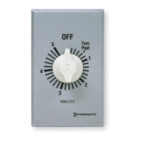
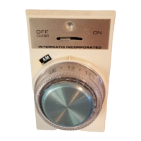
Slip the metal time dial plate over the threaded extension, aligning the 'OFF' mark.

Secure Metal Dial Plate (FF Models)

Fasten the metal dial plate securely to the timer using the provided stamped nut.

Attach Wall Plate (FD Models)

Place the standard toggle or decorator plate on the timer, do not over tighten.

Attach Plastic Time Dial Plate (FD Models)

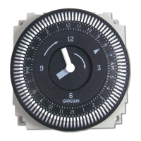
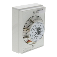
Slip the plastic time dial plate over the threaded extension and secure with the nut.

Set Timer to OFF Position

Push the knob onto the timer shaft, centering the pointer on 'OFF' on the dial plate.

Restore Electrical Power

Turn the electrical power back on at the breaker or fuse panel.

Timer Operation and Applications

Automatic Timing Operation

Turn the timer clockwise to the desired time for automatic shut-off.

Bypass Timer Operation

Turn counterclockwise to stop operation; switch remains 'ON' until manually returned to 'OFF'.

SPST Applications

Used for breaking the hot side of 120-volt loads like coffee pots, lights, and fans.

SPDT Applications

For 3-way switching or reverse action applications, controlling loads from multiple locations.

DPST Applications

For switching both sides of 208, 240, or 277-volt loads like large motors and lighting.

Switch Rating Specifications and Models

Switch Rating Specifications

Details maximum time cycles, voltage, and amperage ratings for different timer configurations.

Available Timer Models

Lists current models for SPST, SPDT, and DPST types, with and without hold features.

Model Prefix and Suffix Changes

Instructions on changing prefixes for decorator style plates and adding suffixes for color options.

Warranty Information

Details the one-year limited warranty, exclusions, and service procedures.

Related product manuals