EasyCoder 201 II – Installation Instructions
3
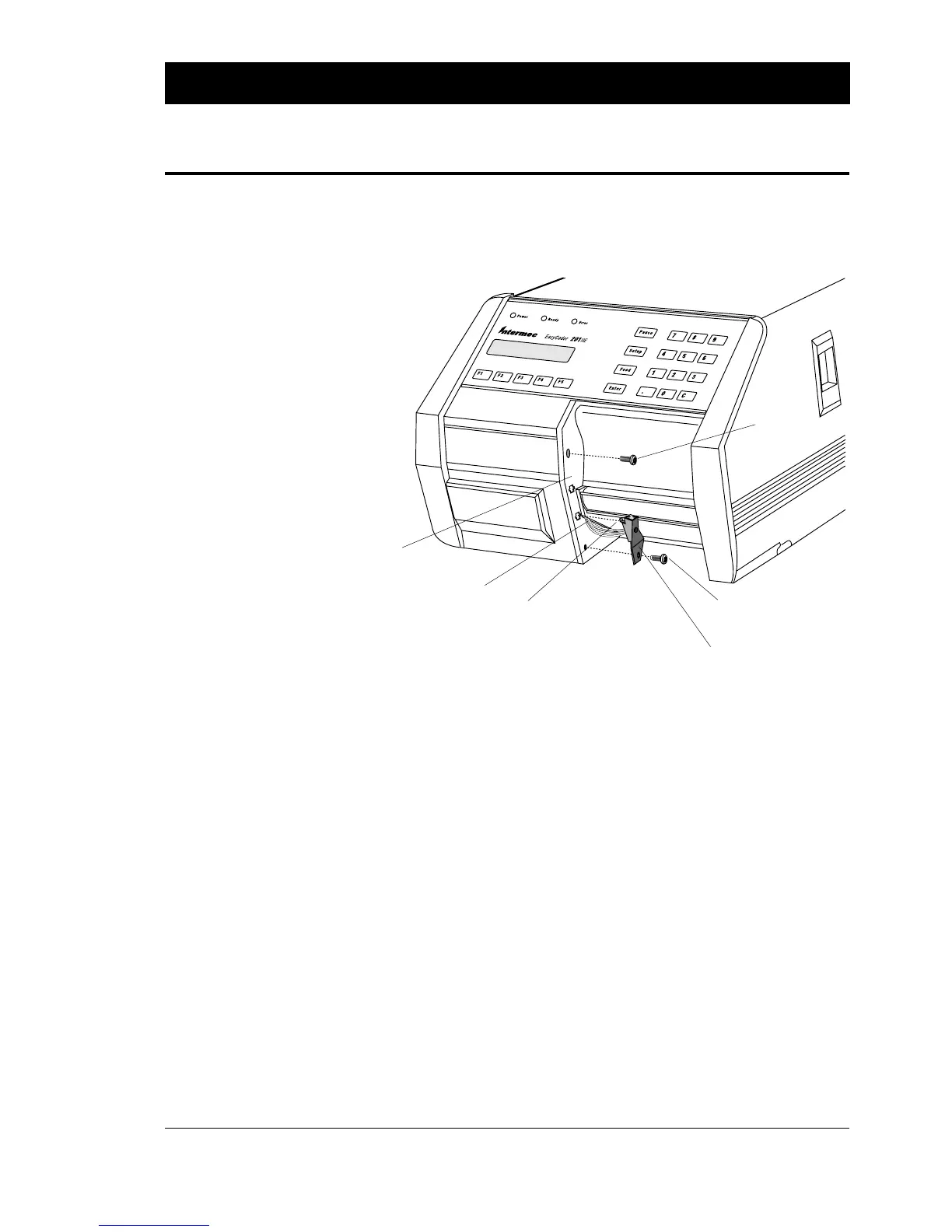
❑ Remove the two screws that hold the front moulding.
❑ Carefully manipulate the moulding so you can slip the cable of
the label-taken sensor through the gap between the moulding
and the centre-line wall of the printer.
❑ Thread the cable back to the electronics compartment and
connect it to P-8 on the CPU board, see next page. Be careful so
the cable will not interfere with the pulley of the print roller or
with the printhead lift mechanism.
❑ Using the screw included in the kit, fit the sensor and the front
moulding as illustrated. The tab at the top of the sensor bracket
should be fitted into the lower of the two cross-shaped holes in
the front moulding.
❑ Put back the original (upper) screw holding the front moulding.
LABEL-TAKEN SENSOR KIT, cont'd.
Step-by-Step Installation
Instructions, cont'd.
LTS assy.
Tab
Front Moulding
Original Screw
Cable
New Screw
(incl. in the kit)
Continued!