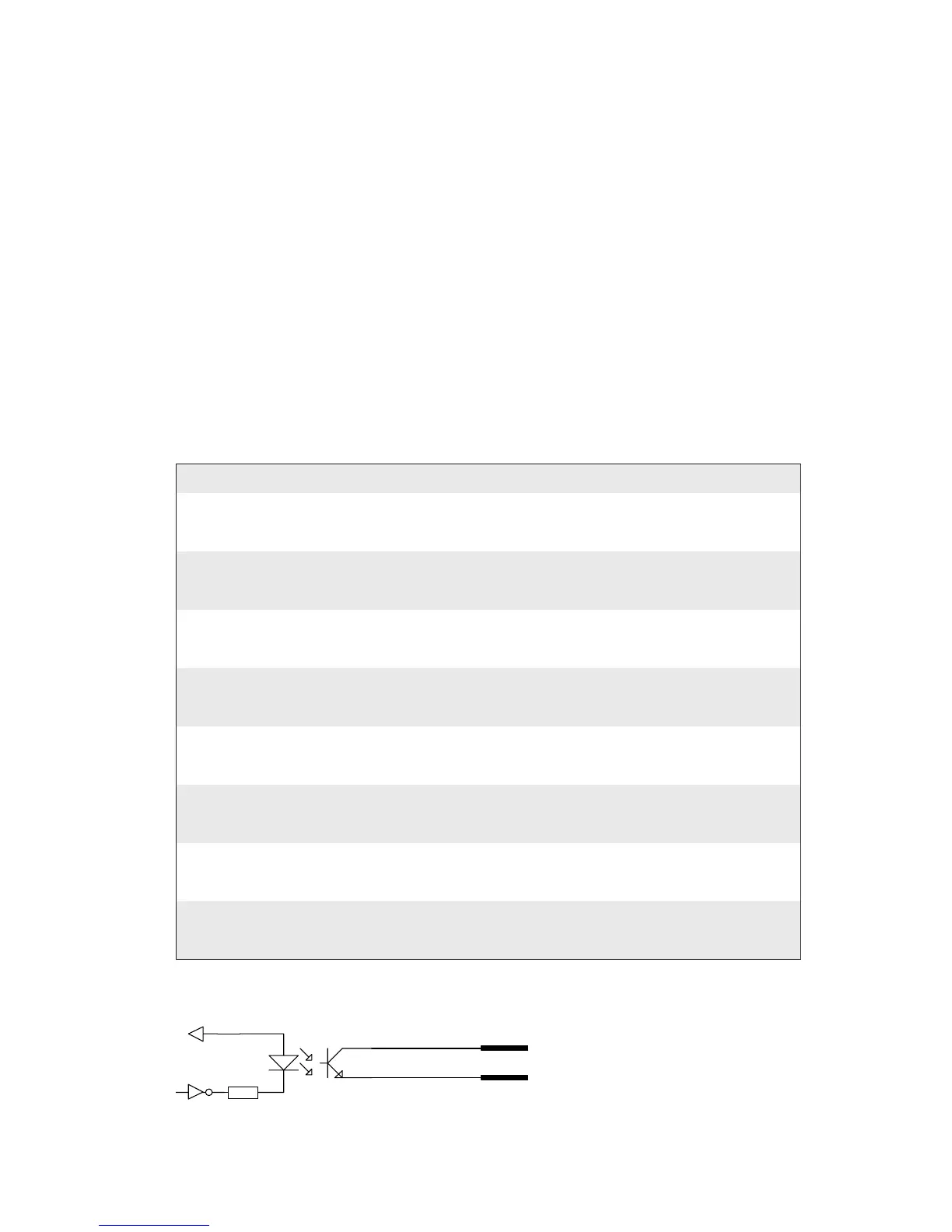
VCC
OUTa
OUTc
Serial/Industrial Interface Kit Installation Instructions 29
Chapter 4 — Industrial Interface
Digital Opto Out
e current to each optocoupler of the digital OUT ports can be turned
on and off using PORTOUT ON/OFF statements.
e status of the ports can be read using PORTIN functions. If a current
is led through the optocoupler of the port, PORTIN returns the value -1
(true), else it returns the value 0 (false).
Signal Description Max.
Vceo Collector-Emitter breakdown voltage 35V
Veco Emitter-Collector breakdown voltage 6V
Collector Current 15 mA
Vog Output to ground (optocoupler) 100V
Connector Confi guration
e Fingerprint reference numbers inside the parentheses refer to a second
Serial/Industrial interface board.
Simplifi ed schematics of a digital OUT port.
Pin Signal Description Fingerprint Ref. No.
20 Out1c Collector Opto Out Channel 1 221 (421)
5 Out1e Emitter Opto Out Channel 1
35 Out2c Collector Opto Out Channel 2 222 (422)
21 Out2e Emitter Opto Out Channel 2
6 Out3c Collector Opto Out Channel 3 223 (423)
36 Out3e Emitter Opto Out Channel 3
22 Out4c Collector Opto Out Channel 4 224 (424)
7 Out4e Emitter Opto Out Channel 4
37 Out5c Collector Opto Out Channel 5 225 (425)
23 Out5e Emitter Opto Out Channel 5
8 Out6c Collector Opto Out Channel 6 226 (426)
38 Out6e Emitter Opto Out Channel 6
24 Out7c Collector Opto Out Channel 7 227 (427)
9 Out7e Emitter Opto Out Channel 7
39 Out8c Collector Opto Out Channel 8 228 (428)
25 Out8e Emitter Opto Out Channel 8