345A
SAVE THESE INSTRUCTIONS
(345IO) SAND FILTER PUMP COMBO ENGLISH 7.5” X 10.3” PANTONE 295U 07/10/2019
English
Page 12
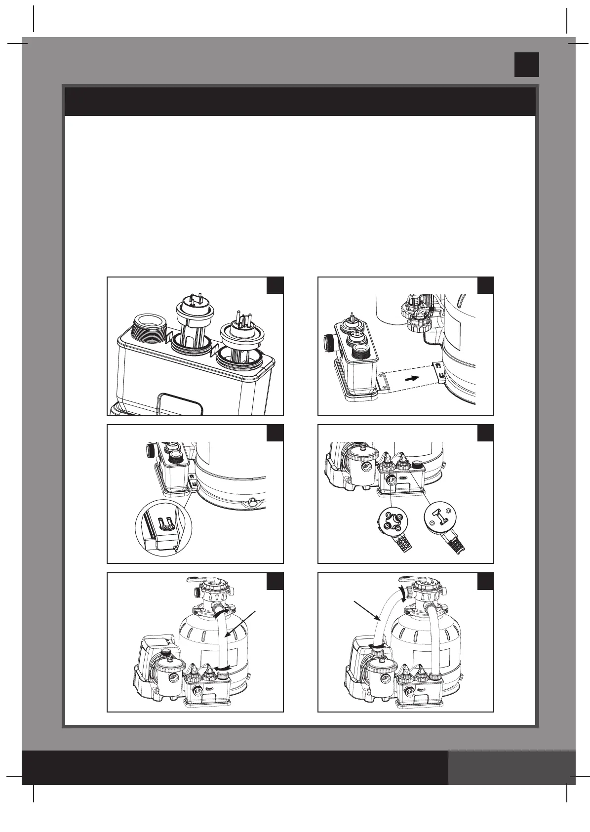
SETUP INSTRUCTIONS (continued)
22
24
26
23
25
27
13
13
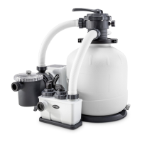
Cell housing installation:
1. Align the notch on the electrodes to the connection ridges in the cell housing electrode
holes. Insert the electrodes into the respective holes (see drawing 22).
2. Attached the cell housing (46) to the tank base (see drawings 23 & 24).
3. Plug in the electrodes’ line cords to the respective electrodes (48 & 49), tighten the plugs
collars and electrodes cell housing collars by hand (see drawing 25).
4. Place an L-shape o-ring (11) on the cell housing inlet and 6-way valve outlet connection.
In a clockwise motion connect the sand filter interconnecting hose (13) between the cell
housing inlet and the 6-way valve outlet connection (see drawing 26).
5. Place an L-shape o-ring (11) on the pump motor outlet and the 6-way valve inlet connection.
In a clockwise motion connect the other sand filter interconnecting hose (13) between the
pump motor outlet and the 6-way valve inlet connection (see drawing 27).
 Loading...