193
PO
SAVE THESE INSTRUCTIONS
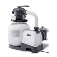
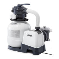
(193PO) MODEL SF90110T SAND FILTER PUMP ENGLISH 7.5” X 10.3” PANTONE 295U 06/21/2013
English
11.2
Page 8
PRODUCT SPECIFICATIONS
SETUP INSTRUCTIONS
Power: 110-120 Volt AC
Amperage: 1.8 A
Maximum working pressure: 1.4 bar (20 psi)
Effective filtering area: 0.05 m
2
(0.54 ft
2
)
Maximum Flow Rate: 4000 liters/hour (1050 gallons/hour)
Recommendedfilteringmedia: No.20silicasandorglasssand.Particlesize
(Notincluded) range0.45to0.85mm(0.018to0.033inches).
Uniformity Coefficient less than 1.75.
Recommendedfilteringmediaquantity: No.20silicasand12Kg(26Lbs)orglasssand
8.5Kg(18.5Lbs).
Limited Warranty: see “Limited Warranty”
NOTE: NOTSUITABLEFORUSEWITHKCP-LOW-SALTAUTOMATICSALTWATERSYSTEM
(MODEL 6110/6220)
The sand filter removes suspended particles but does not sanitize your pool. Pool
chemistry is a specialized area and you should consult your local pool service specialist
for details.
TOOLS REQUIRED: One (1) Phillips screwdriver
Pump location and mounting:
• Thesystemmustbeinstalledonasolidlevelandvibration-freebase.
• Providealocationprotectedfromtheweather,moisture,floodingandfreezing
temperature.
• Provideadequateaccess,spaceandlightingforroutinemaintenance.
• Pumpmotorrequiresfreecirculationofairforcooling.Donotinstallthepumpina
damp or non-ventilated location.
A team of 2 or more people is recommended for setting up this product.
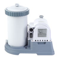
Leaf trap setup:
1. Make sure the pump o-ring (6) is in place. In a clockwise motion screw the leaf trap (19)
onto the motor inlet (see drawing 10).
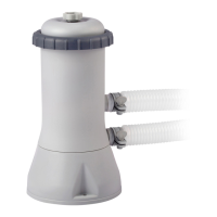
Sand tank installation:
1. Place the tank support base at the selected location.
2. Place the tank on the tank support base (see drawing 11.1).
10
19
6
11.1
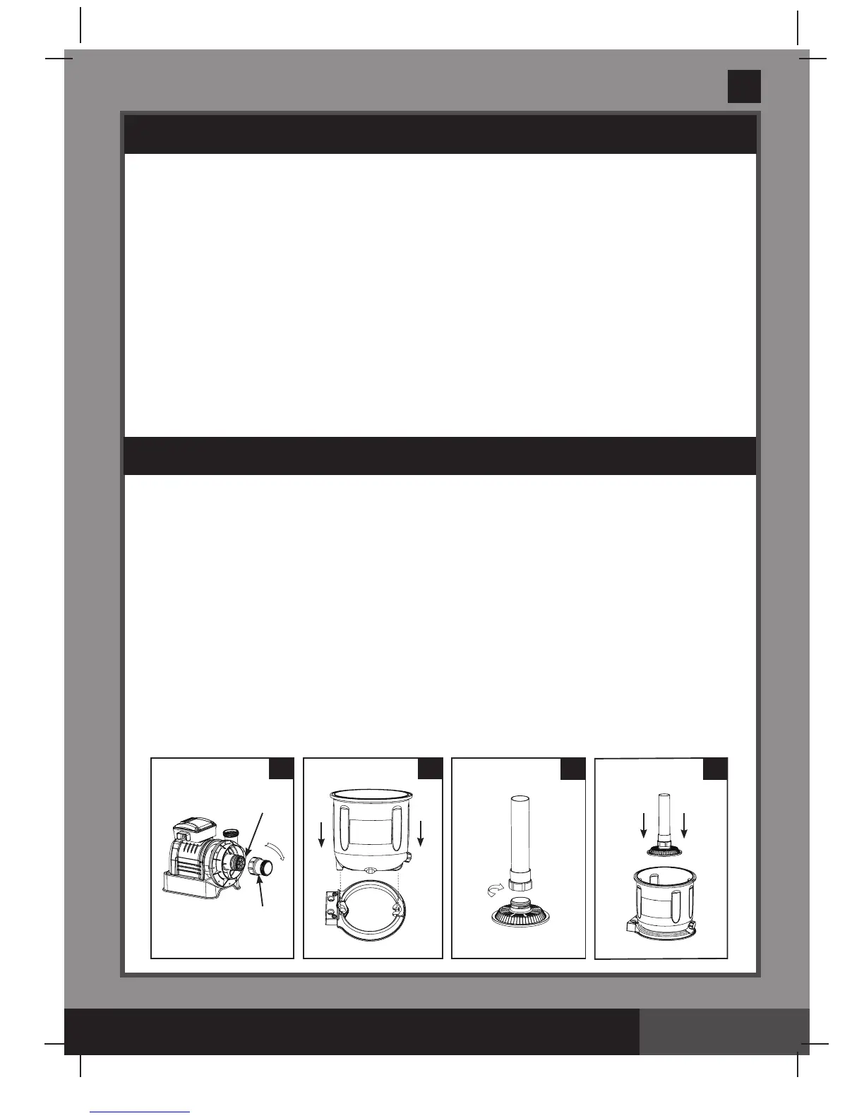
11.3
 Loading...