Mechanical installation4
j | BA 14.0168 | 10/2013
34
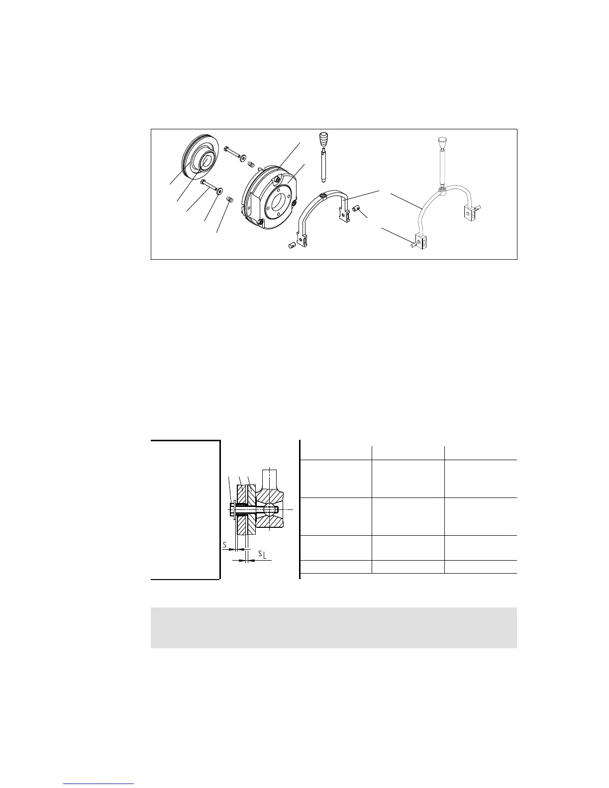
4.5.6 Retrofitting of the manual release
4
14.3
14.2
14.4
3
2
14.5
14.1
1
K14.0630
Fig. 13 Assembly of the manual release BFK458
1. Insert the compression springs (14.2) into the bore holes of the armature plate (2).
2. Push the bolts (14.5) into the bore holes of the shackle (6.1).
3. Push the hexagon head cap screw (14.4) through the compression spring (6.2) in the
armature plate (2) and the bore hole in the stator (1).
4. Screw the hexagon head cap screw (14.4) into the bolts (14.5) in the shackle (14.1).
5. Tighten hexagon screw (14.4) until armature plate (1) moves towards stator (7).
6. Remove the clips (7) (throw away).
7. Adjust gap ”s” and ”s
L”
using the hexagon head cap screw (14.4), (values for ”s” and
”s
L”
see Tab. 7).
Type
1
14 71
s
L
(mm) s+
0.1
(mm) s+s
L
(mm)
BFK458-06
0.2
1 1.2
BFK458-08
BFK458-10
BFK458-12
0.3
1.5 1.8
BFK458-14
BFK458-16
BFK458-18
0.4
2 2.4
BFK458-20
BFK458-25 0.5 2.5 3
Tab. 7 Adjustment setting for manual release
Stop!
Dimension ”s” must be observed! Check air gap ”s
L
”.
 Loading...