j | BA 14.0168 | 10/2013
33
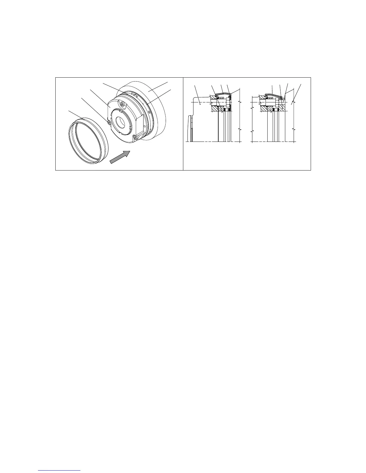
4.5.5 Assembly of the cover seal
15
13
27
10
1
2
12
15
6
13
27
13
10
KL458-010-a KL458-007-a
Fig. 12 Assembly of the cover seal
1 Complete stator 10 Allen screw 15 Endshield
2 Armature plate 13 Cover seal 27 Friction plate
6Flange
1. Insert the cable through the cover ring.
2. Push the cover ring over the stator.
3. Press the lips of the cover ring into the groove of rotor and flange.
– If a friction plate is used, the lip must be pulled over the flanged edge.
 Loading...