Mechanical installation4
j | BA 14.0168 | 10/2013
32
15
6
6.1
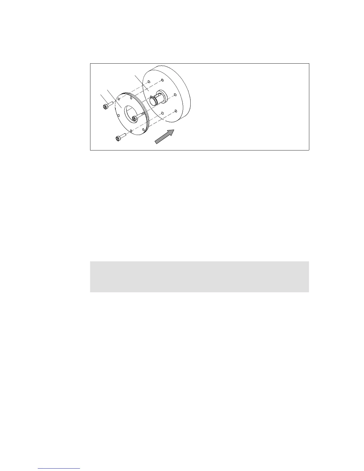
KL458-008-a
Fig. 11 Mounting the f lange
6 Flange 15 End shield
6.1 Set of fastening screws
1. Hold the flange (6) against the end shield (15) and check the pitch circle and retaining
screw drill hole threading.
2. Fasten the flange (6) on the end shield (15) with the screws (6.1).
3. Tighten the cheese head screws (6.1) evenly, (tightening torques 15).
4. Check the height of the screw heads. The screw heads may not be higher than the
minimum rotor thickness. We recommend using screws according to DIN 6912,
dimensions 15.
Mounting the flange without additional screws
Stop!
When dimensioning the thread depth in the end shield, the permissible wear
distance must be taken into consideration 15).
1. Hold the flange (6) against the end shield (15) and check the pitch circle and retaining
screw drill hole threading.
2. Mount the brake with the set of screws provided for this purpose 28 and 52).
 Loading...