j | BA 14.0168 | 10/2013
31
4.5.3 Assembly of the friction plate, sizes 06 to 16
15
27
KL458-009-a
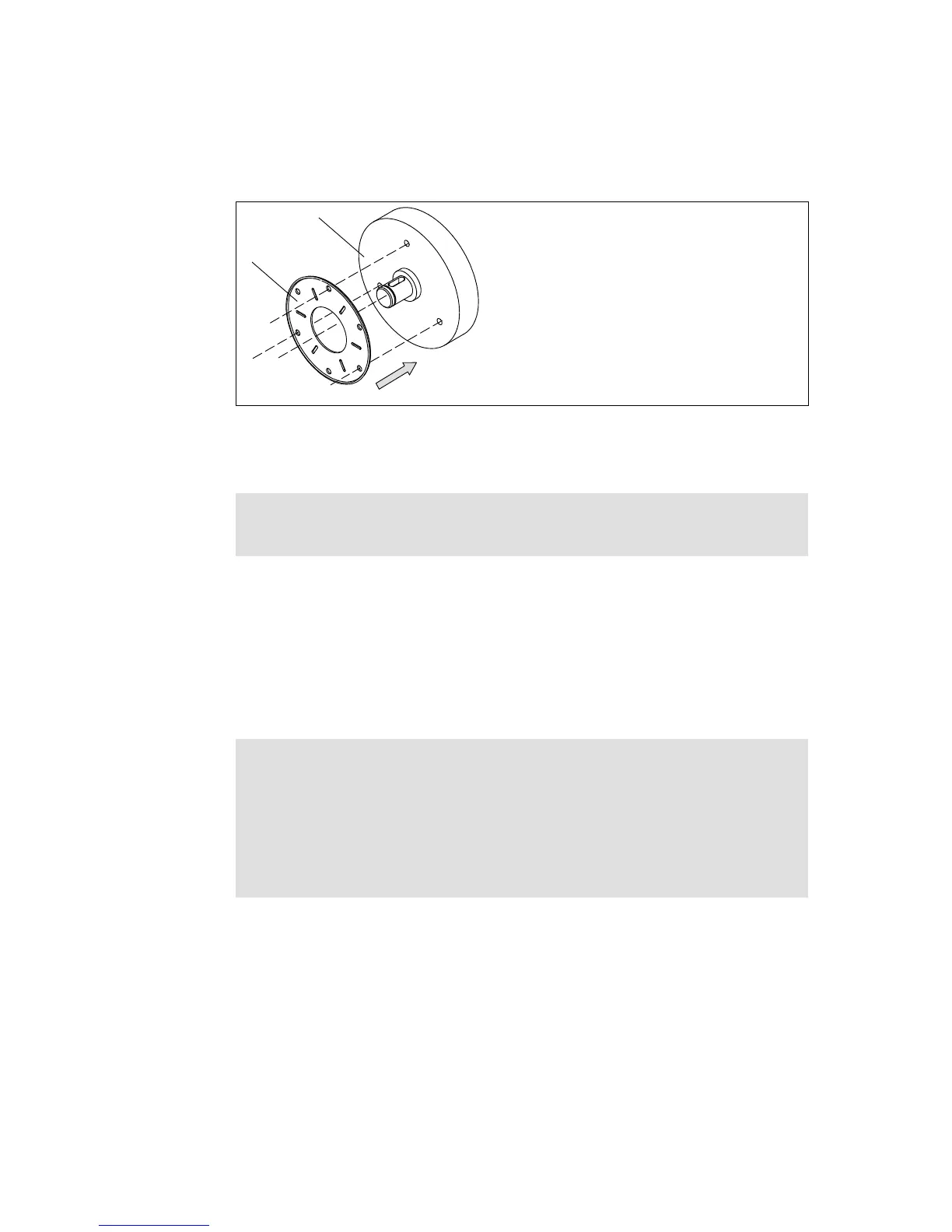
Fig. 10 Mounting the friction plate
15 End shield 27 Friction plate
1. Put a friction plate (27) or flange (6) against the end shield (15).
Note!
The flanged edge of the friction plate must remain visible!
2. Align pitch circle and fastening bore hole thread.
4.5.4 Assembly of the flange
Theflange(6)canbescrewedontheendshield(15)ontheouterpitchcircle(screw
dimensions 15).
Mounting the flange with additional screws
Stop!
| Clearing holes for the screws in the end shield must be behind t he threaded
screw drill-holes in the flange. Without the clearing holes, minimal rotor
thickness cannot be utilised. The screws must not press against the end
shield. (See chapter 3.2 for clearing hole depth)
| For sizes 18 and 20, the fastening surface threading must be angled at 30°
to the centre axis to the manual release lever.
 Loading...