8 PACKAGING, HANDLING AND SET-UP
Part No 1123842 41 Invacare
®
IVC
™
Model BAR600IVC Bariatric Bed
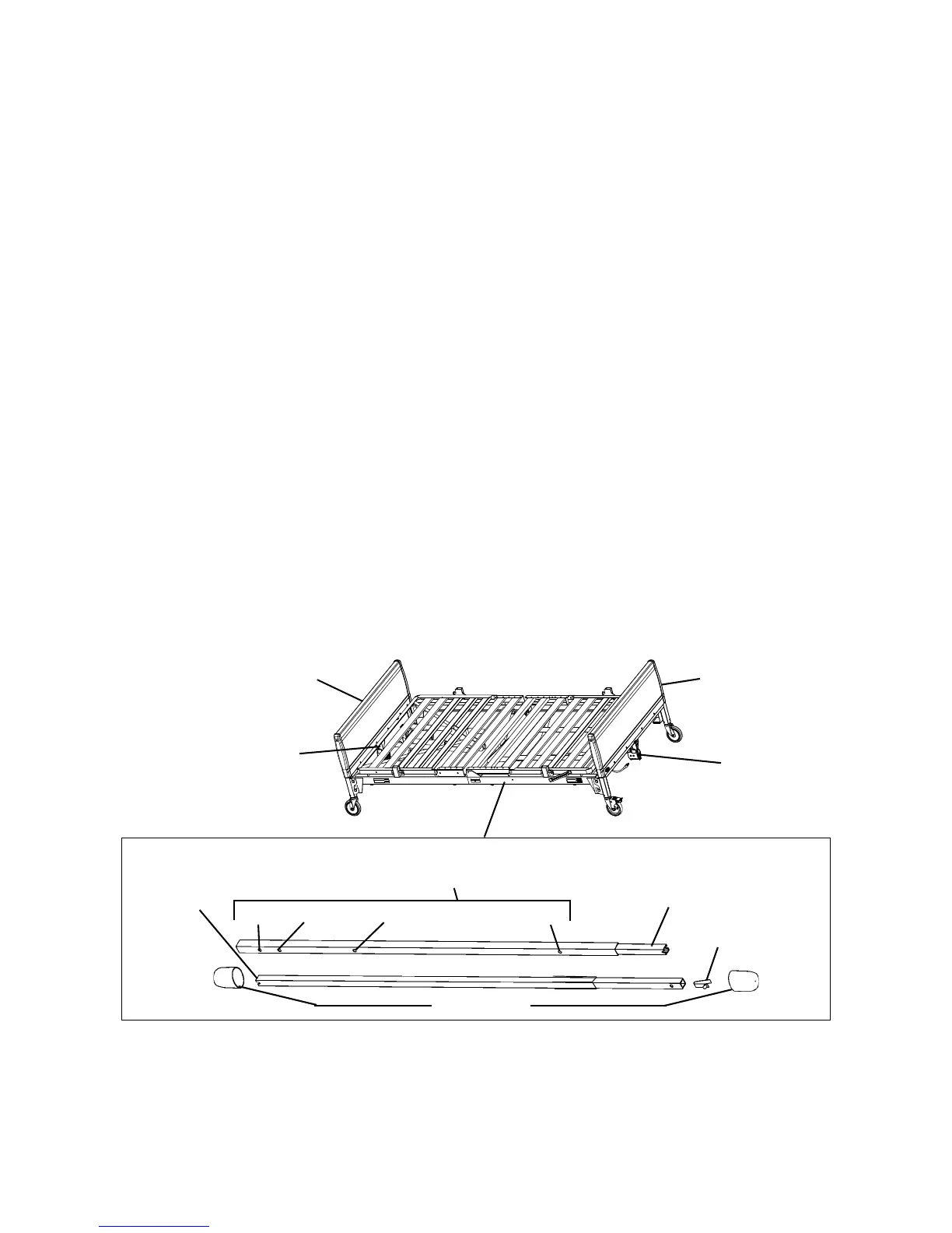
FIGURE9 Assembling/Installing/Removing Drive Shaft
6. Locate the Hi/Lo motor output shaft spring-loaded coupler.
7. Ensure the Hi/Lo motor output shaft spring-loaded coupler is properly aligned with the foot end gear box as shown in Detail “A” of FIGURE10.
If necessary, shift the bed end to the right or left to align the Hi/Lo motor output shaft spring-loaded coupler with the foot
end gear box.




 To Next Page