EasyManuals Logo

INVENTOR EVI-18 Service Manual

INVENTOR EVI-18
101 pages
To Next Page IconTo Next Page
To Previous Page IconTo Previous Page
Page #21 background imageLoading...
Page #21 background image
18
Schematic Diagram
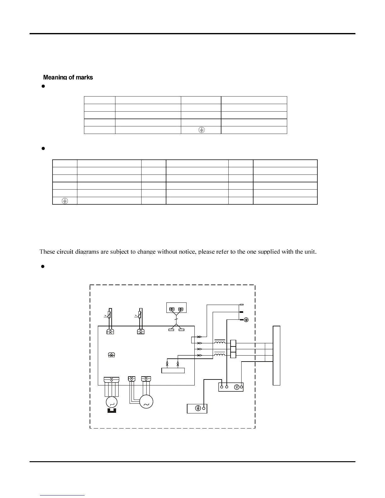
5. Schematic Diagram
5.1 Electrical Date
5.2 Electrical wiring
Outdoor Unit
Indoor Unit
Indoor Unit
OUTDOOR UNIT
MOTOR
FAN
PGF
PG
0
MOTOR
RECEIVER AND
YEGN
BN
BU
L
N
SWING-UD
DISPLAY BOARD
DISP1
4YEGN
COM-OUT
N
0
AP1
TUBE
SWING
TEM. SENSOR
DISP2
JUMP
YEGN
PE
PE
AP2
TUBE
ROOM
TEM. SENSOR
CAP
EVAPORATOR
BU
BK
BN
EARTH-PLATE
L
L
RT1
RT2
M1
BLOCK
TERMINAL
1BU
N(1)
2
XT
3
3BN
2BK
ROOM
M2
L-OUT
AC-L
NO
COM
     
     
     
     
     
  
   
   
   
   
  

Other manuals for INVENTOR EVI-18

Questions and Answers:

Question and Answer IconNeed help?

Do you have a question about the INVENTOR EVI-18 and is the answer not in the manual?

INVENTOR EVI-18 Specifications

General IconGeneral
BrandINVENTOR
ModelEVI-18
CategoryAir Conditioner
LanguageEnglish

Related product manuals