Optidrive ODE-3 1Ph Output User Guide Revision 1.00
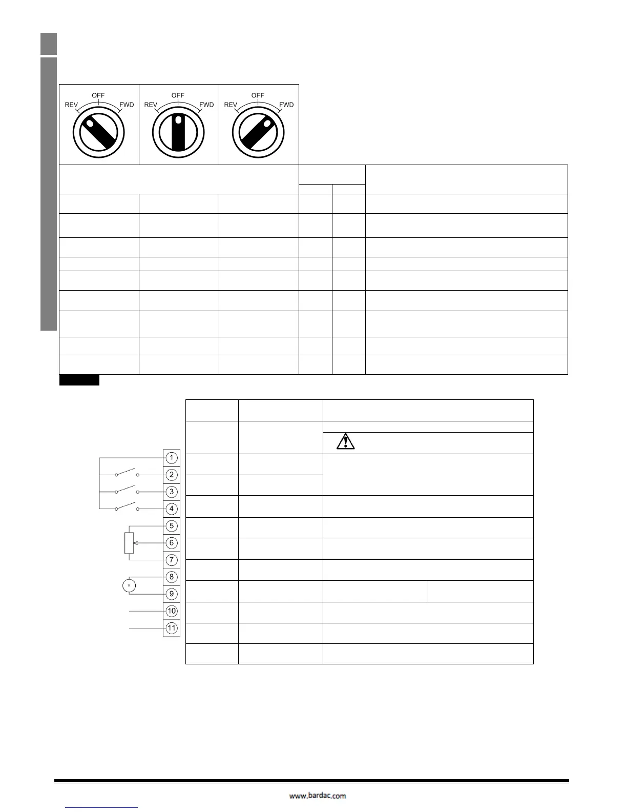
4.9. Using the REV/0/FWD Selector Switch (Switched Version Only)
By adjusting the parameter settings the Optidrive can be configured for multiple applications.
This could typically be for Hand/Off/Auto applications (also known and Local/Remote) for HVAC and pumping industries.
Note : Forward / Reverse operation of single phase motors is not possible
Factory Default Configuration
Run Forward only with speed controlled from the Local POT
Run forward with speed controlled form the local POT or
preset speed
Run Forward with speed controlled from the Local POT or 2
nd
analog input
Local / Remote function with Modbus RTU speed reference
or preset speed,
Selectable PI control or preset speed
Selectable PI control or Pot speed control
Control from CAN interface
Local / Remote function with CAN speed reference or preset
speed,
To be able to adjust parameter P-15, extended menu access must be set in P-14 (default value is 101)
4.10. Control Terminal Connections
+24Vdc user output, 100mA.
Do not connect an external voltage source to
this terminal.
Positive logic
“Logic 1” input voltage range: 8V … 30V DC
“Logic 0” input voltage range: 0V … 4V DC
Digital Input 3 /
Analog Input 2
Digital: 8 to 30V
Analog: 0 to 10V, 0 to 20mA or 4 to 20mA
Analog Input 1 /
Digital Input 4
Analog: 0 to 10V, 0 to 20mA or 4 to 20mA
Digital: 8 to 30V
0 Volt Common, internally connected to terminal 9
Analog Output /
Digital Output
Analog: 0 to 10V,
Digital: 0 to 24V
0 Volt Common, internally connected to terminal 7
Contact 250Vac, 6A / 30Vdc, 5A