EasyManua.ls Logo

INVERTEC optidrive E IP20 - Macro Functions - Keypad Mode (P-12 = 1 or 2); Macro Functions - Fieldbus Control Mode (P-12 = 3, 4, 7, 8 or 9); Macro Functions - User PI Control Mode (P-12 = 5 or 6)

Default Icon
28 pages
Print Icon
To Next Page IconTo Next Page
To Previous Page IconTo Previous Page
Loading...
Optidrive ODE-3 1Ph Output User Guide Revision 1.00
www.invertekdrives.com
23
7
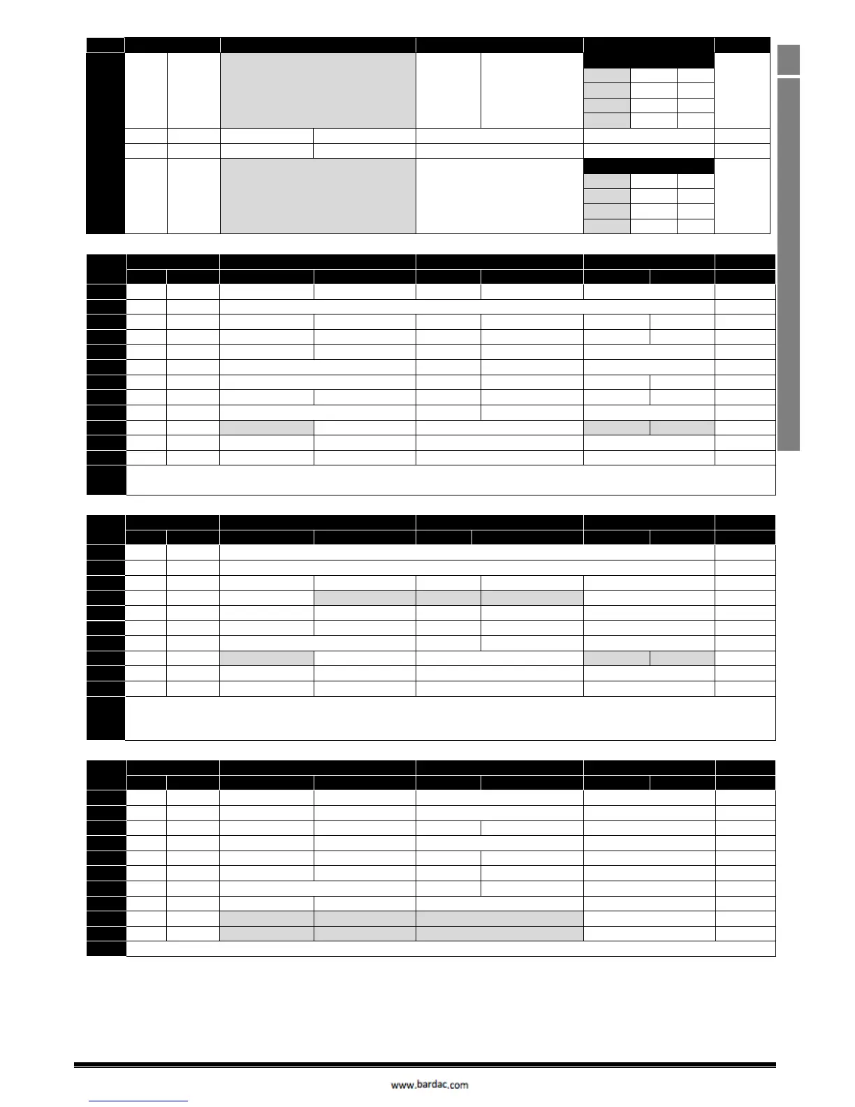
Analog and Digital Input Macro Configurations
P-15
DI1
DI2
DI3 / AI2
DI4 / AI1
Diagram
14
STOP
RUN
DI2
E-TRIP
OK
DI2
DI4
PR
14
0
0
P-20
1
0
P-21
0
1
P-22
1
1
P-23
15
STOP
RUN
P-23 REF
AI1
Fire Mode
Analog Input AI1
2
16
STOP
RUN
P-23 REF
P-21 REF
Fire Mode
No Function
3
17
STOP
RUN
DI2
Fire Mode
DI2
DI4
PR
3
0
0
P-20
1
0
P-21
0
1
P-22
1
1
P-23
7.4. Macro Functions - Keypad Mode (P-12 = 1 or 2)
P-15
DI1
DI2
DI3 / AI2
DI4 / AI1
Diagram
0
1
0
1
0
1
0
1
0
STOP
ENABLE
-
INC SPD
-
DEC SPD
No Function
15
1
STOP
ENABLE
PI Speed Reference
5
2
STOP
ENABLE
-
INC SPD
-
DEC SPD
KPD REF
P-20 REF
15
3
STOP
ENABLE
-
INC SPD
E-TRIP
OK
-
DEC SPD
4
STOP
ENABLE
-
INC SPD
KPD REF
AI1 REF
AI1
6
5
STOP
ENABLE
No Function
KPD REF
AI1 REF
AI1
1
6
STOP
ENABLE
No Function
E-TRIP
OK
KPD REF
P-20 REF
4
7
STOP
ENABLE
OK
FAST STOP (P-24)
E-TRIP
OK
KPD REF
P-20 REF
4
14
STOP
ENABLE
No Function
E-TRIP
OK
No Function
4
15
STOP
ENABLE
PR REF
KPD REF
Fire Mode
P-23
P-21
3
16
STOP
ENABLE
P-23 REF
KPD REF
Fire Mode
No Function
3
17
STOP
ENABLE
KPD REF
P-23 REF
Fire Mode
No Function
3
NOTE
8, 9, 10, 11, 12, 13 = 0
When P-12 = 1 or 2, Refer to P-31 for starting control
7.5. Macro Functions - Fieldbus Control Mode (P-12 = 3, 4, 7, 8 or 9)
P-15
DI1
DI2
DI3 / AI2
DI4 / AI1
Diagram
0
1
0
1
0
1
0
1
0
STOP
ENABLE
FB REF (Fieldbus Speed Reference, Modbus RTU / CAN / Master-Slave defined by P-12)
1
1
STOP
ENABLE
PI Speed Reference
5
3
STOP
ENABLE
FB REF
P-20 REF
E-TRIP
OK
Analog Input AI1
4
5
STOP
ENABLE
FB REF
PR REF
P-20
P-21
Analog Input AI1
2
6
STOP
ENABLE
FB REF
AI1 REF
E-TRIP
OK
Analog Input AI1
4
7
STOP
ENABLE
FB REF
KPD REF
E-TRIP
OK
Analog Input AI1
4
14
STOP
ENABLE
No Function
E-TRIP
OK
Analog Input AI1
4
15
STOP
ENABLE
PR REF
FB REF
Fire Mode
P-23
P-21
3
16
STOP
ENABLE
P-23 REF
FB REF
Fire Mode
Analog Input AI1
2
17
STOP
ENABLE
FB REF
P-23 REF
Fire Mode
Analog Input AI1
2
NOTE
2, 4, 8, 9, 10, 11, 12, 13 = 0
When P-12 = 3 or 4, and P-15 = 5, 6, or 7, when DI 2 is on, DI1 will start and stop the drive.
When P-12 = 3 or 4 and P-31 = 2, 3, 6 or 7, The drive will start / stop based on DI1 only and communication loss is disabled
7.6. Macro Functions - User PI Control Mode (P-12 = 5 or 6)
P-15
DI1
DI2
DI3 / AI2
DI4 / AI1
Diagram
0
1
0
1
0
1
0
1
0
STOP
RUN
PI REF
P-20 REF
AI2
AI1
5
1
STOP
RUN
PI REF
AI1 REF
AI2 (PI FB)
AI1
5
3, 7
STOP
RUN
PI REF
P-20
E-TRIP
OK
AI1 (PI FB)
4
4
(NO)
START
(NC)
STOP
AI2 (PI FB)
AI1
5
(NO)
START
(NC)
STOP
PI REF
P-20 REF
AI1 (PI FB)
11
6
(NO)
START
(NC)
STOP
E-TRIP
OK
AI1 (PI FB)
14
STOP
RUN
No Function
E-TRIP
OK
AI1 (PI FB)
1
15
STOP
RUN
P-23 REF
PI REF
Fire Mode
AI1 (PI FB)
2
16
STOP
RUN
P-23 REF
P-21 REF
Fire Mode
AI1 (PI FB)
2
17
STOP
RUN
P-21 REF
P-23 REF
Fire Mode
AI1 (PI FB)
2
NOTE
2, 8, 9, 10, 11, 12, 13 = 0

Table of Contents