Application note AN-ODE-2-045
AN-ODE-2-045 Using Multiple Motors In Parallel
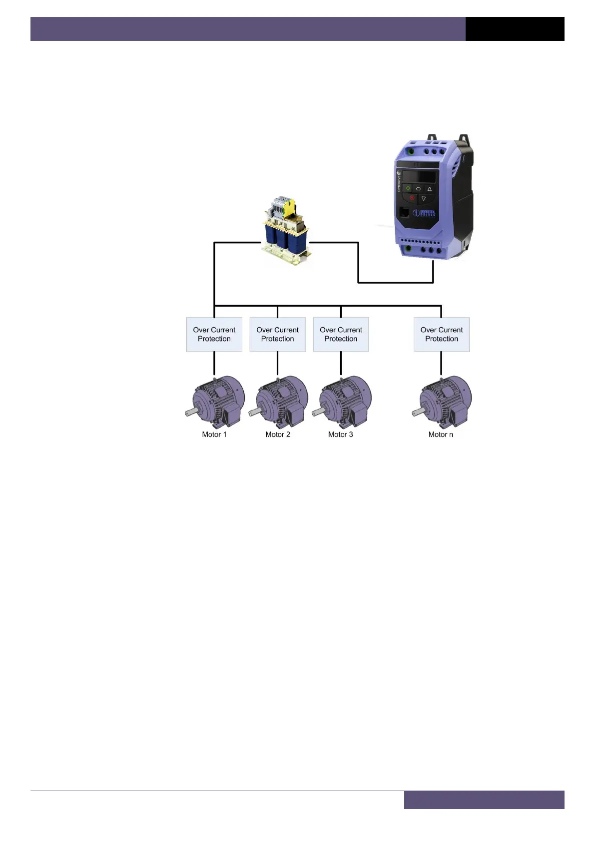
Wiring Configurations
The diagrams below shows a common installation setup where a single drive is used to control a larger (>1) number of smaller
rated motors.
Configuration 1: Series Connection
With this connection method a single motor cable is run between the drive and the first motor and connection is then daisy
chained from one motor to the next. The cable from the drive to the first motor is therefore typically long and is required to be
rated to the combined current [A] ratings of all of the over-current protection devices. This configuration typically results in the
Over-current protection being located close to the motor it protects, making the cable run between the over-current protection
and the associated motor very short.
The output filter is required only when the accumulative motor cable length is greater than the maximum motor cable length
specified for the drive (given in the drive operating manual).
Optional Output Filter
(Not required if total motor cable length is less
than maximum specified in drive manual)