Optidrive ODE-2 User Guide Revision 3.30
3.8. Gland Plate and Lock Off
The use of a suitable gland system is required to maintain the appropriate IP / Nema rating. The gland plate has pre moulded cable entry
holes for power and motor connections suitable for use with glands as shown in the following table. Where additional holes are required,
these can be drilled to suitable size. Please take care when drilling to avoid leaving any particles within the product.
Cable Gland recommended Hole Sizes & types:
Flexible Conduit Hole Sizes:
UL rated ingress protection ("Type " ) is only met when cables are installed using a UL recognized bushing or fitting for a flexible-
conduit system which meets the required level of protection ("Type")
For conduit installations the conduit entry holes require standard opening to the required sizes specified per the NEC
Not intended for rigid conduit system
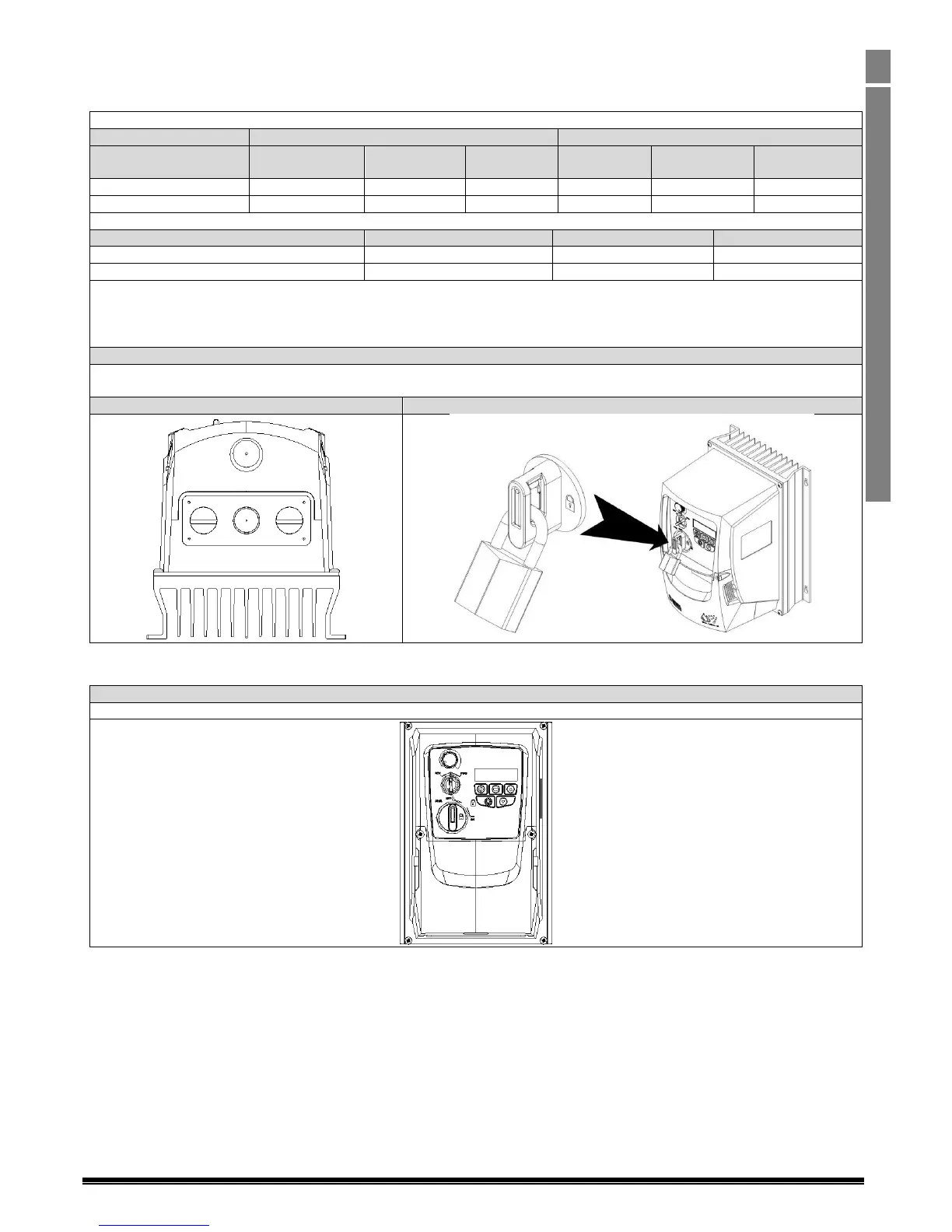
On the switched models the main power isolator switch can be locked in the ‘Off’ position using a 20mm standard shackle padlock (not
supplied).
IP66 / Nema 4X Gland Plate
IP66 / Nema 4X Unit Lock Off
3.9. Removing the Terminal Cover
To access the connection terminals, the drive front cover needs to be removed as shown.
Removing the 2 screws on the front of the product allows access to the connection terminals, as shown below.
3.10. Routine Maintenance
The drive should be included within the scheduled maintenance program so that the installation maintains a suitable operating environment,
this should include:
Ambient temperature is at or below that set out in the “Environment” section.
Heat sink fans freely rotating and dust free.
The Enclosure in which the drive is installed should be free from dust and condensation; furthermore ventilation fans and air filters
should be checked for correct air flow.
Checks should also be made on all electrical connections, ensuring screw terminals are correctly torqued; and that power cables have no signs
of heat damage.

 Loading...


