Optidrive ODE-2 User Guide Revision 3.30
Modbus RTU Communications
8. Modbus RTU Communications
8.1. Introduction
The Optidrive E2 can be connected to a Modbus RTU network via the RJ45 connector on the front of the drive.
8.2. Modbus RTU Specification
9600bps, 19200bps, 38400bps, 57600bps, 115200bps (default)
1 start bit, 8 data bits, 1 stop bits, no parity.
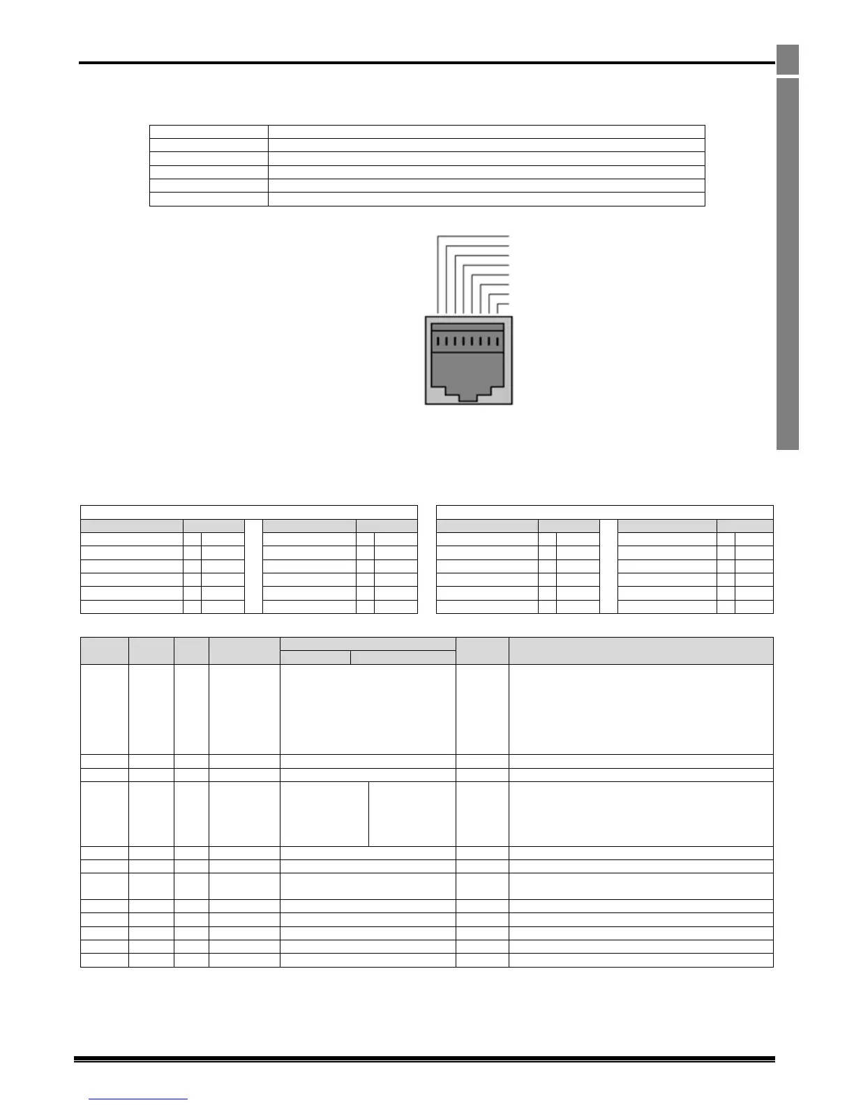
8.3. RJ45 Connector Configuration
For full MODBUS RTU register map
information please refer to your Invertek
Drives Sales Partner.
When using MODBUS control the Analog and
Digital Inputs
can be configured as shown in section 7.3
Warning:
This is not an Ethernet
connection. Do not connect
directly to an Ethernet port.
8.4. Modbus Telegram Structure
The Optidrive ODE-2 supports Master / Slave Modbus RTU communications, using the 03 Read Holding Registers and 06 Write Single Holding
Register commands. Many Master devices treat the first Register address as Register 0, therefore it may be necessary to convert the Register
Numbers detail in section 8.5 by subtracting 1 to obtain the correct Register address. The telegram structure is as follows:-
Command 03 – Read Holding Registers
Command 06 – Write Single Holding Register
16 Bit Word.
Bit 0 : Low = Stop, High = Run Enable
Bit 1 : Low = Decel Ramp 1 (P-04), High = Decel
Ramp 2 (P-24)
Bit 2 : Low = No Function, High = Fault Reset
Bit 3 : Low – No Function, High = Coast Stop
Request
Modbus Speed reference setpoint
Setpoint frequency x10, e.g. 100 = 10.0Hz
Acceleration and Deceleration Time
Ramp time in seconds x 100, e.g. 250 = 2.5 seconds
Low Byte = Drive Error Code, see section 10.1
High Byte = Drive Status as follows :-
0 : Drive Stopped
1: Drive Running
2: Drive Tripped
Output frequency in Hz x10, e.g. 100 = 10.0Hz
Output Motor Current in Amps x10, e.g. 10 = 1.0 Amps
Indicates the status of the 4 digital inputs
Lowest Bit = 1 Input 1
Analog input % of full scale x10, e.g. 1000 = 100%
Analog input % of full scale x10, e.g. 1000 = 100%
Displays the setpoint frequency x10, e.g. 100 = 10.0Hz
Drive heatsink temperature in ºC
All user configurable parameters are accessible as Holding Registers, and can be Read from or Written to using the appropriate Modbus
command. The Register number for each parameter P-04 to P-047 is defined as 128 + Parameter number, e.g. for parameter P-15, the register
number is 128 + 15 = 143. Internal scaling is used on some parameters, for further details, please contact your Invertek Drives Sales Partner.

 Loading...


