Optidrive ODE-2 User Guide Revision 3.30
4.6. Motor Thermal overload Protection.
4.6.1. Internal Thermal Overload Protection.
The drive has an in-built motor thermal overload function; this is in the form of an “I.t-trP” trip after delivering >100% of the value set in P-08
for a sustained period of time (e.g. 150% for 60 seconds).
4.6.2. Motor Thermistor Connection
Where a motor thermistor is to be used, it should be connected as follows :-
Additional Information
Compatible Thermistor : PTC Type, 2.5kΩ trip level
Use a setting of P-15 that has Input 3 function as External Trip, e.g. P-15 = 3. Refer to section 7 for
further details.
4.7. Control Terminal Wiring
All analog signal cables should be suitably shielded. Twisted pair cables are recommended.
Power and Control Signal cables should be routed separately where possible, and must not be routed parallel to each other.
Signal levels of different voltages e.g. 24 Volt DC and 110 Volt AC, should not be routed in the same cable.
Maximum control terminal tightening torque is 0.5Nm.
Control Cable entry conductor size: 0.05 – 2.5mm
2
/ 30 – 12 AWG.
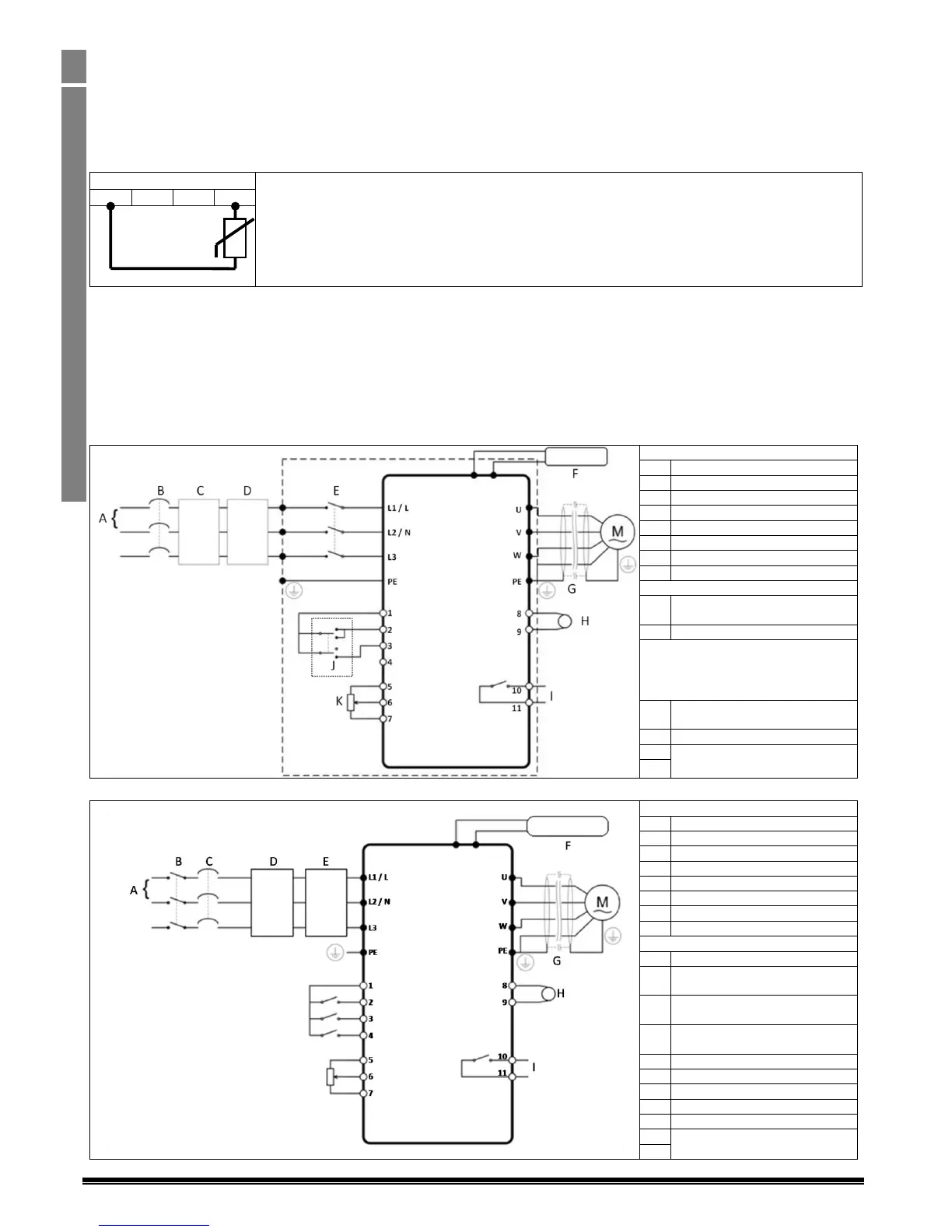
4.8. Connection Diagram
4.8.1. IP66 (Nema 4X) Switched Units
Internal Isolator / Disconnect
Internal Forward / Off / Reverse
Switch
Internal Speed Control Pot
Analog Output
0 – 10 Volts
Relay Output
‘Drive Healthy’ = Closed
4.8.2. IP20 & IP66 (Nema 4X) Non- Switched Units
+ 24 Volt (100mA) User Output
Digital Input 1
Drive Run / Stop
Digital Input 2
Forward / Reverse
Digital Input 3
Analog / Preset Speed
Analog Output 0 – 10 Volts
Relay Output
‘Drive Healthy’ = Closed

 Loading...


