Goodrive20-EU series VFD Function parameters
88
Detailed instruction of parameters
2: Cycle running. The VFD will keep on running
until receiving a stop command and then, the
system will stop.
Simple PLC
memory
selection
0: Power loss without memory
1: Power loss memory; PLC record the running
stage and frequency when power loss.
100.0% of the frequency setting corresponds to
the max. frequency P00.03.
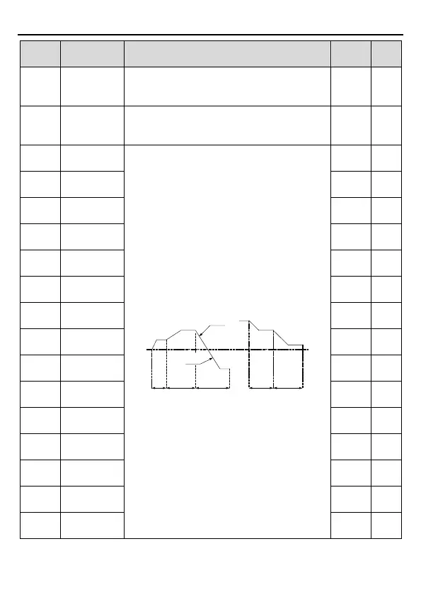
When selecting simple PLC running, set P10.02
– P10.33 to define the running frequency and
direction of all stages.
Note: The symbol of multi-step determines the
running direction of simple PLC. The negative
value means reverse rotation.
P10.04
P10.02
P10.03
P10.05 P10.07
P10.06
P10.31 P10.33
P10.32
ACC time
2 stages
DEC time
2 stages
P10.30
P10.28
multi-step speeds are in the range of --f
max
– f
max
and it can be set continuously.
Goodrive20-EU series VFDs can set 16 stages
speed, selected by the combination of multi-step
terminals 1 – 4, corresponding to the speed 0 to
speed 15.

 Loading...


