Goodrive300 Series VFD Communication protocol
210
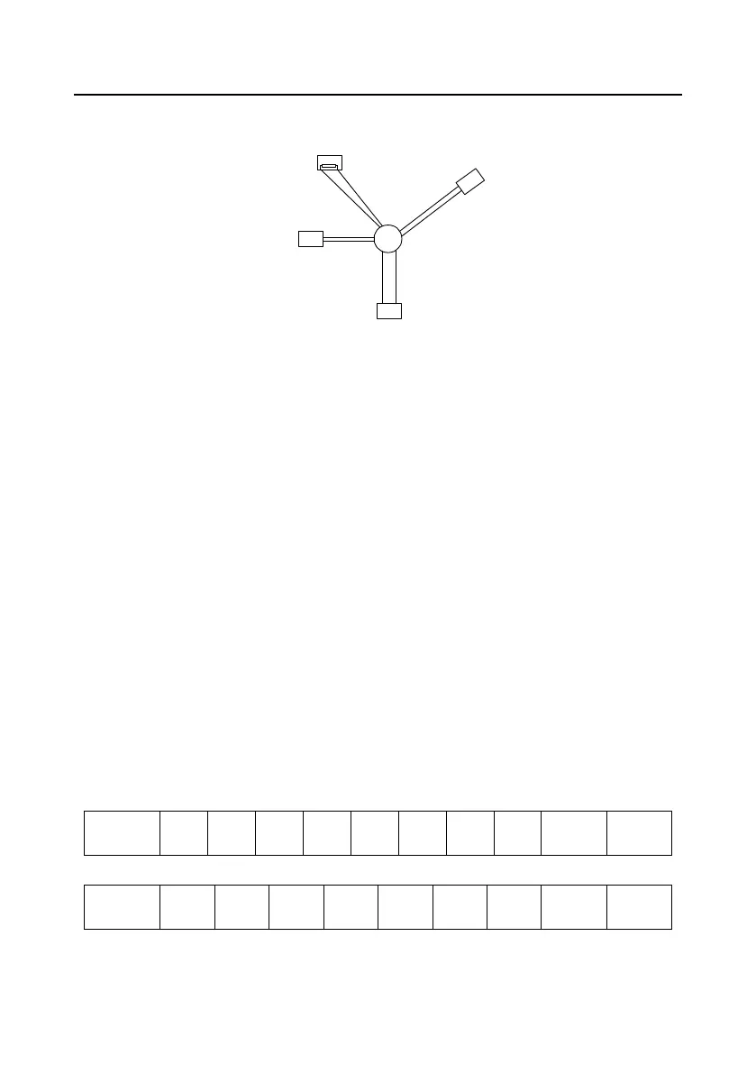
Figure 5 is the star connection. Terminal resistor should be connected to the two devices which have
the longest distance. (1# and 15#device)
1 #
15 #
32 #
6
#
Main control
devices
Figure 10-5 star connection
It is recommended to use shield cables in multiple connection. The basic parameter of the devices,
such as baud rate and digital check bit in RS485 should be the same and there should be no repeated
address.
10.3.2 RTU mode
10.3.2.1 RTU communication frame format
If the controller is set to communicate by RTU mode in Modbus network every 8bit byte in the
message includes two 4Bit hex characters. Compared with ACSII mode, this mode can send more
data at the same baud rate.
Code system
· 1 start bit
· 7 or 8 digital bit, the minimum valid bit can be sent firstly. Every 8 bit frame includes two hex
characters (0...9, A...F)
· 1 even/odd check bit . If there is no checkout, the even/odd check bit is inexistent.
· 1 end bit (with checkout), 2 Bit (no checkout)
Error detection field
· CRC
The data format is illustrated as below:
11-bit character frame (BIT1–BIT8 are the data bits)
10-bit character frame (BIT1–BIT7 are the data bits)
In one character frame, the digital bit takes effect. The start bit, check bit and end bit is used to send
the digital bit right to the other device. The digital bit, even/odd checkout and end bit should be set as

 Loading...


