Goodrive300 Series VFD Extension card
241
11:Fault code
12: AI1 value (×100, V)
13: AI2 value (×100, V)
14: AI3 value (×100, V)
15: PULSE frequency value (×100,
kHz)
16:Terminals input state
17:Terminals output state
18: PID given (×100, %)
19: PID feedback (×100, %)
20: Motor rated torque
21: Control word
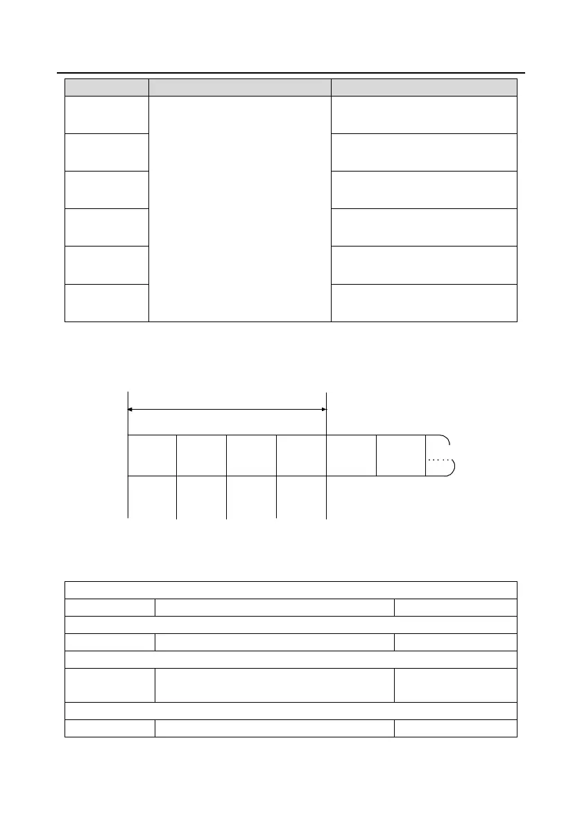
PKW area (parameter identification marks PKW1-value area). PKW area describes treatment of
parameter identification interface, PKW interface is a mechanism which determine parameters
transmission between two communication partners, such as reading and writing parameter values.
Structure of PKW area
Parameter identification (PWK)
Process data
PKW1 PKW2 PKW3 PKW4
CW
SW
PZD2
PZD2
Request label
Response
label
Parameter
address
Parameter
value error
number
Parameter
value
Parameter identification zone
In the process of periodic PROFIBUS-DP communication, PKW area is composed of four words (16
bit), each word is defined as follows:
The first word PKW1 (16 bit)
Task or response identification marks
The second word PKW2 (16 bit)
The third word PKW3 (16 bit)
Parameter value (high word) or return error code
value
The fourth word PKW4 (16 bit)
Parameter value (low word)