Goodrive300 Series VFD Installation guide
24
output filter are optional parts. Please refer to Appendix D "Peripherial options and parts" for detailed
information.
A1 and A2 are standard parts.
P1 and (+) are short circuited in factory, if it needs to connect with the DC rector, please remove
the contact tag between P1 and (+).
Before connecting the braking resistor cable, remove the yellow labels of PB, (+), and (-) from
the terminal blocks. Otherwise, poor connection may occur.
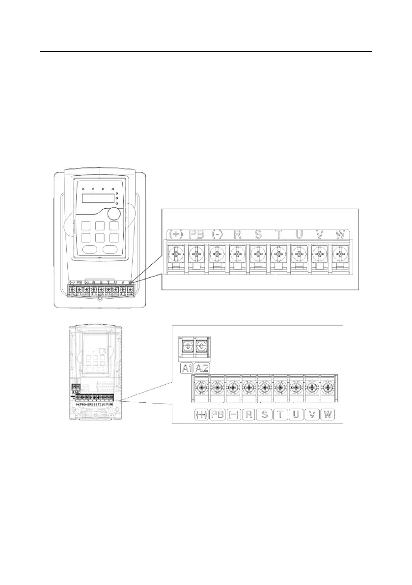
4.3.2 Main circuit terminals diagram
Figure 4-10 Main circuit terminals diagram of VFDs of 380V (1.5–2.2kW)
Figure 4-11 Main circuit terminals diagram of VFDs of 380V (4–5.5kW)

 Loading...


