Goodrive300 Series VFD Installation guide
23
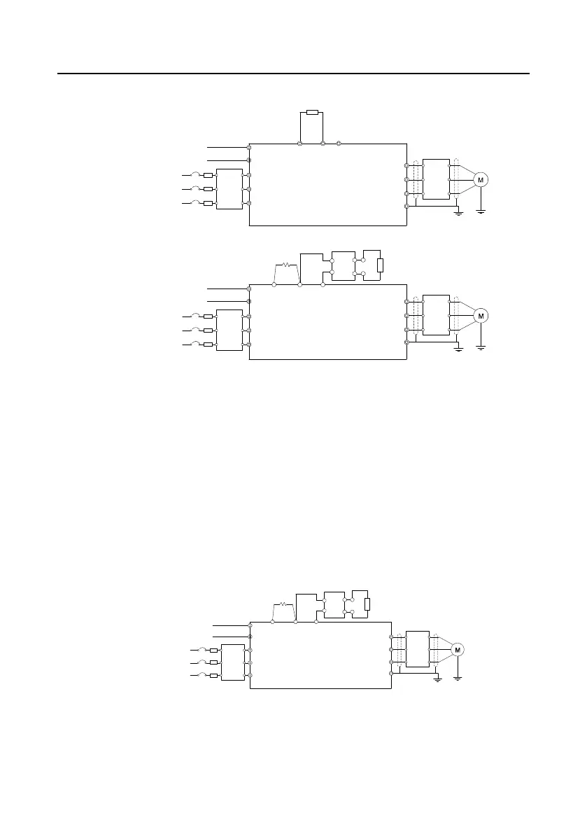
4.3.1.2 Main circuit connection diagram of VFDs of 3PH 380V (-10%)–550V (+10%)
Brake resistor
Single-phase 220V
(optional)
A1
A2
AC 3PH
380V (-10%)–550V (+10%)
50/60 Hz
Single-phase 220V
(optional)
AC 3PH
380V (-10%)–550V (+10%)
50/60 Hz
A1
A2
Fuse
Input
reactor
Input
filter
Input
reactor
Input
filter
Fuse
R
S
T
Output
reactor
Output
filter
Output
reactor
Output
filter
(+)
PB
(-)
(+)
P1
(-)
DC+
DC-
Brake resistor
R
S
T
U
V
W
PE
U
V
W
PE
DC reactor
VFDs (≤18.5 kW)
VFDs (≥22kW)
Brake unit
Figure 4-8 Connection diagram of main circuit for the VFDs of 500V
Note:
The fuse, DC reactor, braking unit, braking resistor, input reactor, input filter, output reactor,
output filter are optional parts. Please refer to Appendix D "Peripherial options and parts" for detailed
information.
A1 and A2 are optional parts.
P1 and (+) are short circuited in factory for the VFDs of 500V (≥22kW), if need to connect with
the DC rector, please remove the contact tag between P1 and (+).
Before connecting the braking resistor cable, remove the yellow labels of PB, (+), and (-) from
the terminal blocks. Otherwise, poor connection may occur.
4.3.1.3 Main circuit connection diagram of VFDs of AC 3PH 520V (-15%)–690V (+10%)
Brake unit
Single-phase 220V
(standard)
A1
A2
AC 3PH
520V (-15%)–690V (+10%)
50/60 Hz
Input
reactor
Input
filter
Fuse
Output
reactor
Output
filter
(+)
(-)
U
V
W
PE
VFDs (≥37 kW)
Brake resistor
P1
DC reactor
DC+
DC-
R
S
T
Figure 4-9 Connection diagram of main circuit for the VFDs of 660V
Note:
The fuse, DC reactor, braking unit, braking resistor, input reactor, input filter, output reactor,
 Loading...


