4. Fasten up all the cables on the outside of the VFD if allowed.
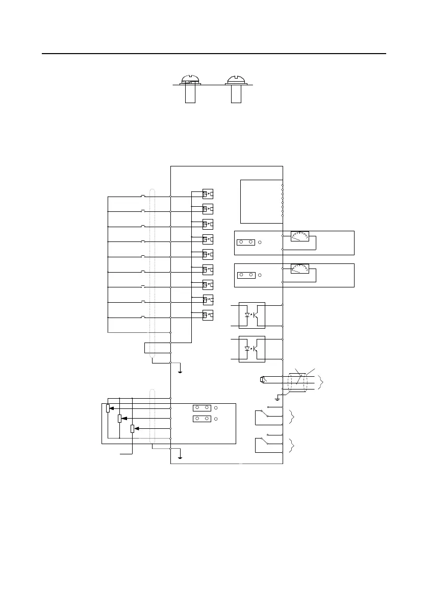
Multi-function input terminal 1
High-speed pulse output and
open collector output (optional)
Open collector output
CME
CME
Y1
Shielding layer
Twisted pairs
S1
S2
S3
S4
S5
S6
S7
S8
HDI
COM
PW
+24V
PE
+10V power supply for setting frequency
AI1
AI2
AI3 multi-function analog input
GND
PE
–10V
(external)
Multi-function input terminal 2
Multi-function input terminal 3
Multi-function input terminal 4
Multi-function input terminal 5
Multi-function input terminal 6
Multi-function input terminal 7
Multi-function input terminal 8
High-speed pulse input collection
Open collector input
Goodrive300 VFD
V
I
V
I
J3
J4
485+
485-
RO1A
RO1B
RO1C
RO2A
RO2B
RO2C
Profibus
External
extension card
(optional)
Standard
DB9 plug
V
I
J1
V
I
J2
AO1
DND
AO2
DND
AO
0–10V/0–20mA
AO
0–10V/0–20mA
HDO
J5
GND
PE
RO1
RO2
RS485
communication
 Loading...


