Goodrive300 Series VFD Installation guide
30
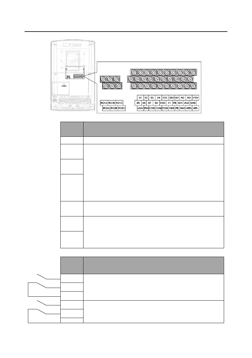
4.3.5 Control circuit terminal diagram
Figure 4-22 Control circuit terminals
1. Input range: AI1/AI2 voltage and current can be chosen: 0–10
V/0–20mA; AI1 can be shifted by J3 while AI2 can be shifted by J4;
AI3: -10 V–+10 V
2. Input impedance: voltage input: 20kΩ; current input: 500Ω
3. Resolution: the minimum one is 5m V when 10 V corresponds to
50 Hz
4. Deviation ±1%, 25°C
+10 V reference null potential
1. Output range: 0–10 V or 0–20mA; The voltage or the current
output is depended on the jumper. AO1 is switched by J1 and AO2 is
switched by J2
2. Deviation±1%, 25°C
RO1 relay output; RO1A is NO, RO1B is NC, RO1C is common port
Contact capacity: 3A/AC250V, 1A/DC30V
RO2 relay output; RO2A is NO, RO2B is NC, RO2C is common port
Contact capacity: 3A/AC250V, 1A/DC30V
 Loading...


