What does high DC injection mean in my INVT iMars BG12KTR?
- JJoseph WestSep 9, 2025
High DC injection in your INVT Inverter means there is high DC injection during AC output.
What does high DC injection mean in my INVT iMars BG12KTR?
High DC injection in your INVT Inverter means there is high DC injection during AC output.
What does low isolation impedance mean for INVT Inverter?
Low isolation impedance in your INVT Inverter means there's low isolation impedance in the external port system.
What does internal communication fault mean for INVT Inverter?
Internal communication fault in your INVT Inverter indicates that master-slave DSP communication is disabled or there is an error in the master-slave DSP check bit.
What does manual shutdown mean for INVT iMars BG12KTR?
Manual shutdown of your INVT Inverter means it was stopped by the operation panel or upper PC.
What does DC power reversed mean for INVT iMars BG12KTR?
DC power reversed means that the DC power is reversed.
Explains warning symbols used in the manual for device and personal safety.
Provides essential safety instructions for installation, operation, and maintenance of the inverter.
Describes the components and function of a solar grid-tied power generation system.
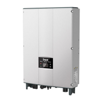
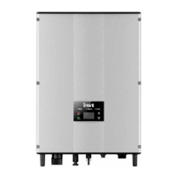
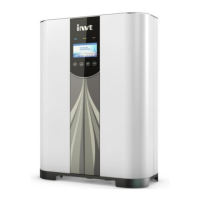
Details the physical appearance and components of the iMars series inverters.
Explains the information found on the inverter's nameplate for identification.
Provides instructions for Digital Ready Mode (DRM) functions for grid control.
Lists the different models of the iMars grid-tied solar inverter available.
Presents the physical dimensions and weight of the inverter and its packaging.
Guides the user through checking the inverter and its accessories after unpacking.
Covers preparations and tools required before the physical installation of the inverter.
Details the process of physically mounting the inverter to a wall or bracket.
Explains the procedures for connecting solar modules and AC power to the inverter.
Outlines checks required before starting the inverter's operation.
Describes the steps for operating the inverter in grid-tied mode and initial setup.
Details the procedure for safely stopping the inverter for maintenance or other needs.
Provides guidance on routine daily maintenance tasks for the inverter's longevity.
Explains the meaning and function of the LED indicators on the inverter's panel.
Describes the buttons and their functions on the inverter's operation panel for control.
Details the information displayed on the inverter's LCD screen and its navigation.
Covers how to view and set various parameters and functions via the LCD and panel.
Explains the standard RS485 communication methods for monitoring the inverter.
Describes optional communication modes like Ethernet and WiFi for monitoring.
Details the RS485-DRM ports and their pin configurations for specific control.
| Start Voltage | 200 V |
|---|---|
| Number of MPPTs | 2 |
| Number of DC Inputs per MPPT | 2 |
| Rated Grid Frequency | 50/60 Hz |
| THDi | <3% |
| MPPT Efficiency | 99.9% |
| DC Switch | Yes |
| Protection Degree | IP65 |
| Weight | 28 kg |
| Frequency Range | 50/60 Hz |
| Model | BG12KTR |
| MPPT Voltage Range | 200-850 V |
| Rated AC Output Power | 12000W |
| Max. AC Output Power | 13200W |
| Power Factor | 0.8 leading - 0.8 lagging |
| Operating Temperature Range | -25 ~ +60 °C |
| Communication | RS485 |
| Protection | DC reverse polarity |
| Storage Temperature | -40 ~ +70 °C |
| Humidity | 0-100% |


