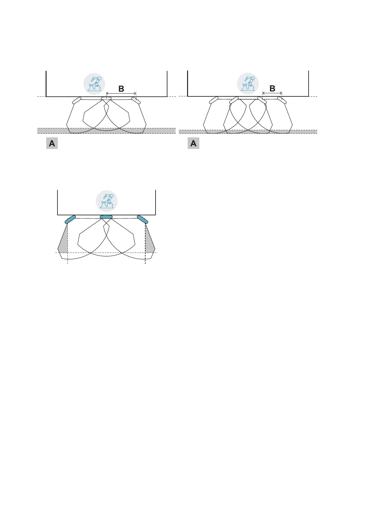
6.2.3 Distance of sensors and tolerance area
The tolerance area [A] increases as the distance between the sensors [B] increases, up to a maximum of 20
cm approximately.
6.2.4 Side areas and false alarms
Given the geometry of the field of vision, areas subject to false alarms are generated in the side areas of the
dangerous area.
The machinery designer must enclose these areas to prevent transit in the area and thus avoid false alarms.
The distance for installation of the delimiting barriers can be calculated based on the parameters provided by
the Inxpect Safety application during the configuration phase.
6.2.5 Calculation of the monitored area
The monitored area is calculated automatically by the Inxpect Safety application. Given the dimensions of the
dangerous area and any pre-alarm area, the system calculates:
l the number of necessary sensors
l the sensors installation distance
l the rotation angle of the sensor around the vertical axis
l the total depth of the monitored area (dangerous area + pre-alarm area + tolerance area)
l the total width of the monitored area (dangerous area + possible distance of side delimiting barriers)
l the depth of the tolerance area
To calculate the depth of the dangerous area, "Dangerous area calculation" on page27.
6. Applications
LBK System| Instruction manual v1.3 SEP 2019 |LBK-System_instructions_en v1.3|© 2018-2019 Inxpect SpA
37