62
LBK System| Instruction manual v1.3 SEP 2019 |LBK-System_instructions_en v1.3|© 2018-2019 Inxpect SpA
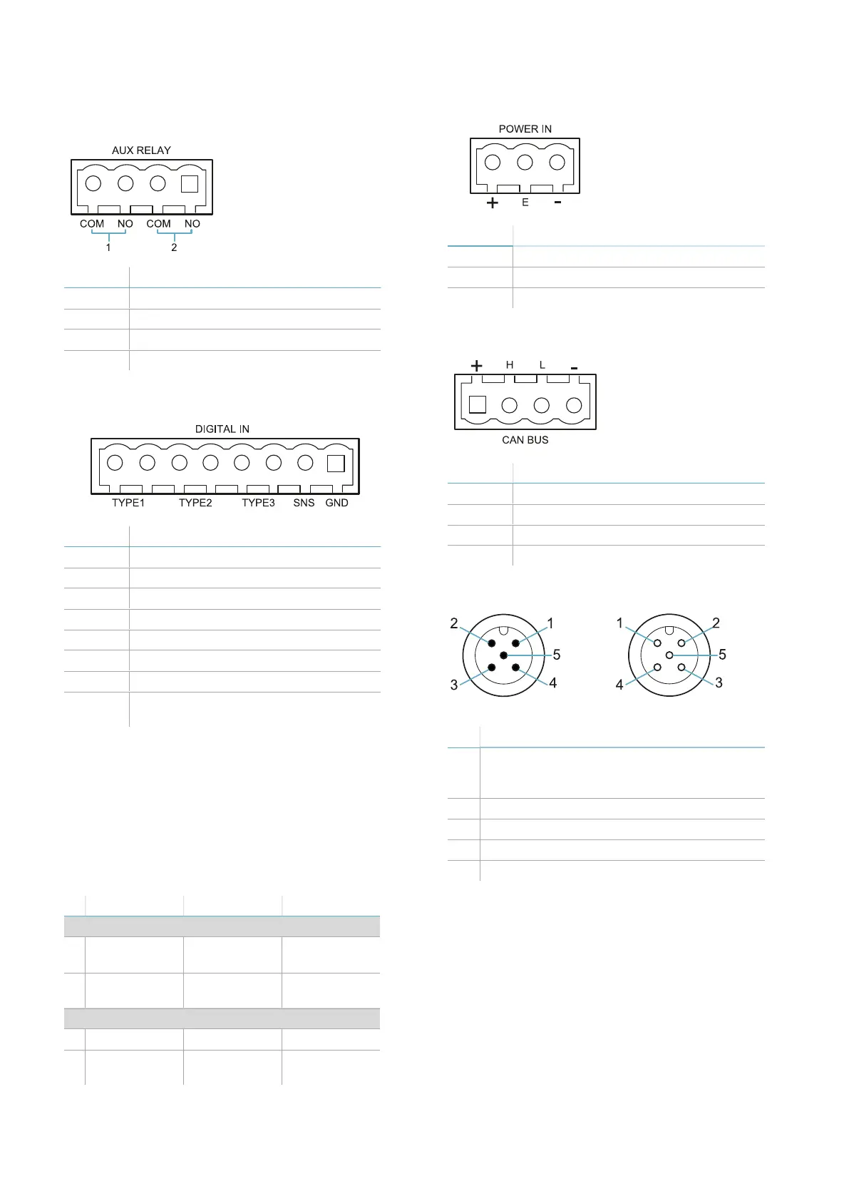
9.2.2 Auxiliary outputs terminal
block
Terminal Description
COM Common auxiliary output 1
NO Relay output normally open
COM Common auxiliary output 2
NO Relay output normally open
9.2.3 Digital inputs terminal block
Terminal Description
Type 1
Input 24 V dc type 1
Type 1
Input 24 V dc type 1
Type 2
Input 24 V dc type 2
Type 2
Input 24 V dc type 2
Type 3 Input 24 V dc type 3
Type 3 Input 24 V dc type 3
SNS Input 24 V dc for diagnostics
GND Common reference for all digital
inputs
Note: the cables used must have a maximum length of 30
m.
9.2.4 Voltage and current limits
for digital inputs
The digital inputs (input voltage 24 V dc) adhere
to the following voltage and current limits, in
accordance with standard EN 61131-2:2003.
Type 1 Type 2 Type 3
Voltage limits
0 from - 3 to 15
V
from - 3 to 11
V
from - 3 to 11
V
1 from 15 to 30
V
from 11 to 30
V
from 11 to 30
V
Current limits
0 15 mA 30 mA 15 mA
1 from 2 to 15
mA
from 6 to 30
mA
from 2 to 15
mA
9.2.5 Power supply terminal block
Terminal Description
+
+ 24 V dc
E
Earth
-
GND
9.2.6 CAN bus terminal block
Terminal Description
+ + 12 V dc
H CAN H
L CANL
- GND
9.2.7 Connectors M12 CAN bus
Male connector Female connector
Pin Function
1 Shield, to be connected to earth circuit
power supply terminal block of the
controller.
2 +12 V dc
3 GND
4 CAN H
5 CAN L
9. Technical references