Introduction
9
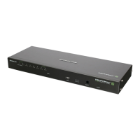
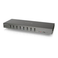
3. CPU Port Section – The cables that link the switch to your computers plug in here. Each CPU port is
comprised of a microphone jack, speaker jack, and KVM data connector.
Note: The shape of these 15-pin connectors has been specifically modified so that only KVM cables
designed to work with this switch can plug in. Do NOT attempt to use ordinary 15 pin VGA connector
cables to link these ports to the computers.
4. Cable Tie Slot – If you want to use a cable tie to gather the cables, you can run it through this
slot to attach it to the unit.
5. Power Jack – The power adapter cable plugs into this jack.
 Loading...