12
PART 5: PRETESTING CHECKLIST
The pretesting checklist should always be completed prior to using the MUTT
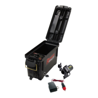
UNIT PLACEMENT
• Place the tester on a at, level surface.
• Chock trailer wheels to avoid rolling.
MAINTAIN CONNECTORS
Dielectric grease should be used on all connections to avoid corrosion. If a bad
connection exists at the terminal junction, you may get an erroneous reading and
the MUTT will not work properly.
• Make sure you have a solid connection in the socket.
• Be certain the 7 pins in each plug are clean and spread to the proper size.
• Always check the MUTT connector pins at the side of the MUTT for proper
expansion. Over time, the pins may bend in slightly resulting in a poor connection
between the connector and the cable ends. A at head screwdriver can be used
to expand the pins until a tight connection is made.
CABLE TESTING PROCEDURE
The MUTT has a special cable feature to test 7-way round pin cables for continuity.
The cable testing feature can be used to test a tractor’s cable, or the supplied MUTT
cable. All cables should be tested prior to MUTT operation.
• Insert each end of the cable into both side connectors on the MUTT. Be sure to
push the cable ends in rmly until they reach the bottom of the connector.
• Turn main power switch to a desired power supply.
• Once the power is selected, the green lights around the control knob will blink
and disappear one at a time until only the Ground Integrity Indicator remains solid
green. Once the initial check has been performed, poor cable conditions will be
shown by a blinking light for the problem circuit.
• If the cable has an open circuit or continuity problem, the corresponding circuit will
ash repeatedly.
• Further testing can be performed by selecting each circuit individually via the
control knob or remote. When an open circuit is detected, the LED for the circuit
will ash and an audible alert will be heard.