Technisch manual IPC MicroTimer IPC Systems B.V.
Technisch manual IPC MicroTimer Pagina 34
Versie 1.3
Ontwikkelingsspecificaties, wijzigingen voorbehouden Datum 14-03-‘02
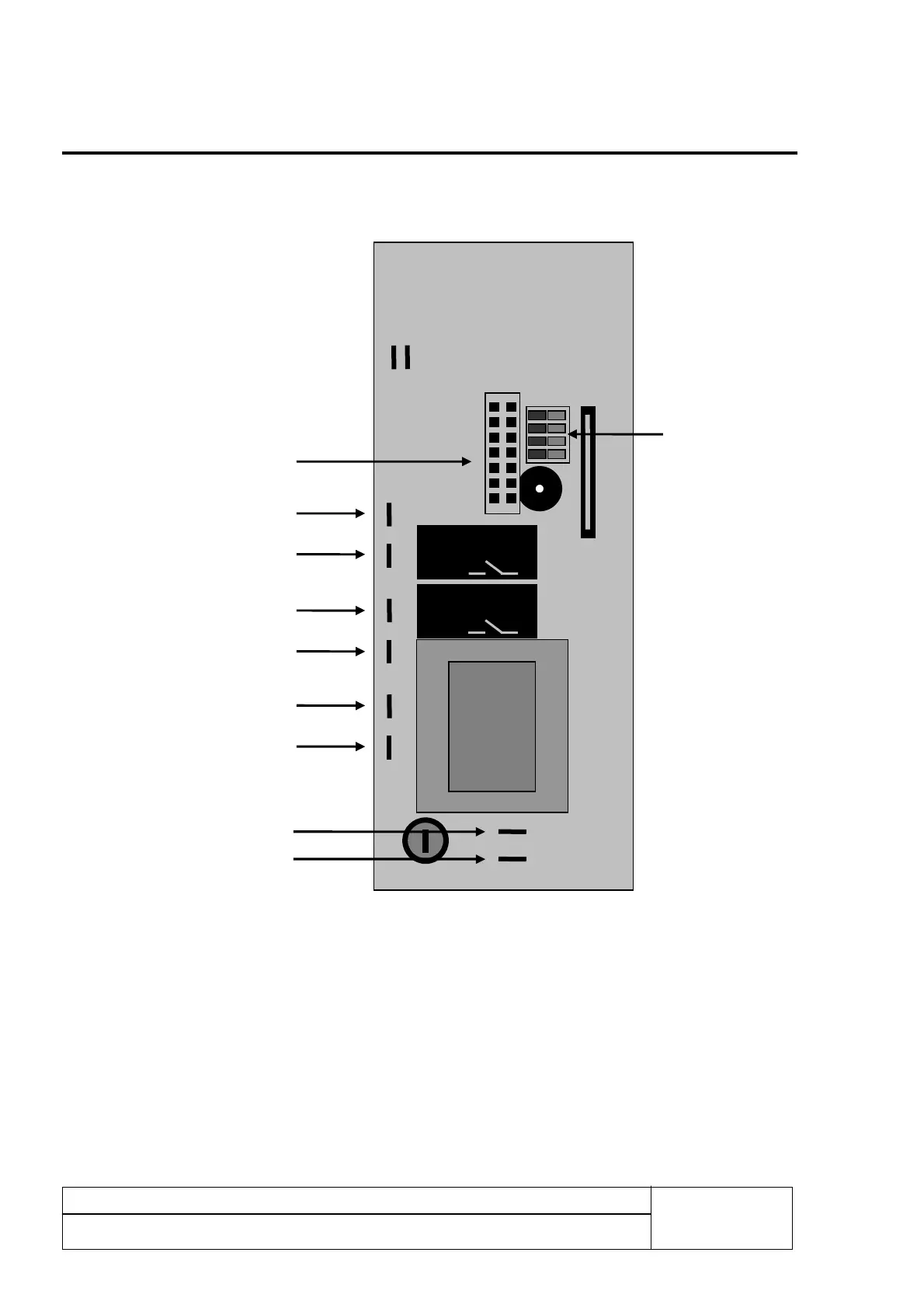
Table de connexions électriques: 4
Connexions des signaux de contrôle sur l'arrière de la plaque:
*Fonctionnement Dipswitch : 1 = On Bouton Stop présent
1 = Off Bouton Stop absent
2 = On Bouton Timer présent
2 = Off Bouton Timer absent
3 = On Bouton Start / Pause présent
3 = Off Bouton Start / Pause absent
4 = On la modification des configurations est possible
4 = Off la modification des configurations n'est pas possible
Relais 1 max.
6,3A
Relais 2 max.
6,3A
Alimentation
230V AC
Sortie relais1
Sortie relais 2
Alimentation
24V AC/DC
Bouton de démarrage
externe connexion after
start pcb
Dipswitchen *