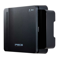
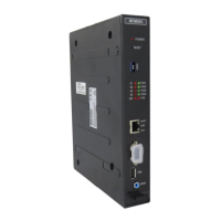
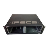
iPECS eMG800
Hardware Description and Installation Manual Issue 1.8
64
4.5.1.1 Switch, and LED Functions
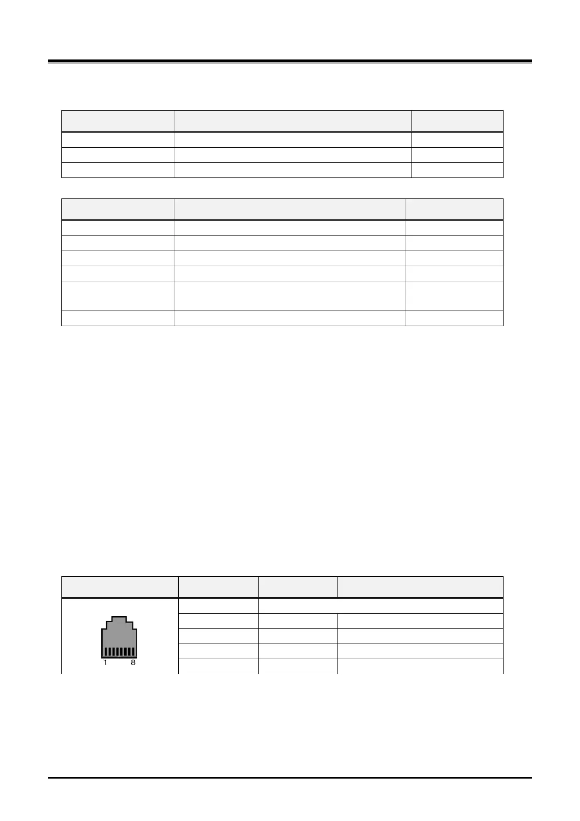
Table 4.5.1.1-1 Switch Functions
4-POLE Dip Switch (Function: not defined)
Table 4.5.1.1-2 LED Indication
Normal operation indication (Activity Indication)
Memory Full (ON – Full, OFF – Usable)
Record (ON – Active, OFF – Idle)
Play (ON – Active, OFF – Idle)
ON – Link, Blink – Data Transfer
ON - 100Mbps, OFF – 10Mbps
4.5.1.2 VMIB and AAIB Installation
VMIB and AAIB have no switches or connectors that are field useable. VMIB and AAIB can be installed in any
universal slot of any KSU; the 1st slot of the BKSU is for MPB only.
1) Assure Power is OFF
2) Slide the VMIB/AAIB in the guide rails of the desired slot.
3) Tighten thumbscrews to hold the board firmly in place.
4.5.1.3 VMIB and AAIB Wiring
There is no wiring required for proper operation of the VMIB or AAIB.
4.5.1.4 VMIB and AAIB LAN Connector
The VMIB and AAIB include an RJ45 for connection to a 10/100 Base-T Ethernet (IEEE 802.3) connection.
The port supports auto negotiation for speed (10 or 100 Mbps) and full or half-duplex operation. If need be, the
RJ45 is wired as indicated in the RJ45 pin-out chart below.
Table 4.5.1.4-1 VMIB & AAIB RJ45 Pin-out Chart
4.5.1.5 Serial Port
The VMIB and AAIB include an Audio jack connected to a Serial port. The serial port is used for diagnostic
purposes. For wiring information, refer to section 4.6.



 To Next Page