Page 09
ASSEMBLY
NOTE:
Handle already is assembled on the unit.
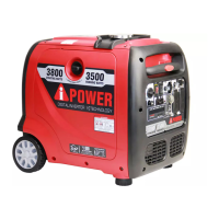
IMPORTANT: Before operating the generator the
shock-absorbing seat (K) must be adjusted for
clearance. Loosen the lock nut (L) and adjust the
shock absorbing seat (K) so there is about 3-4mm
gap between the top of the seat and the bottpm of
the alternator bracket (M). Re-tighten the lock nut
after adjustment.
3-4mm
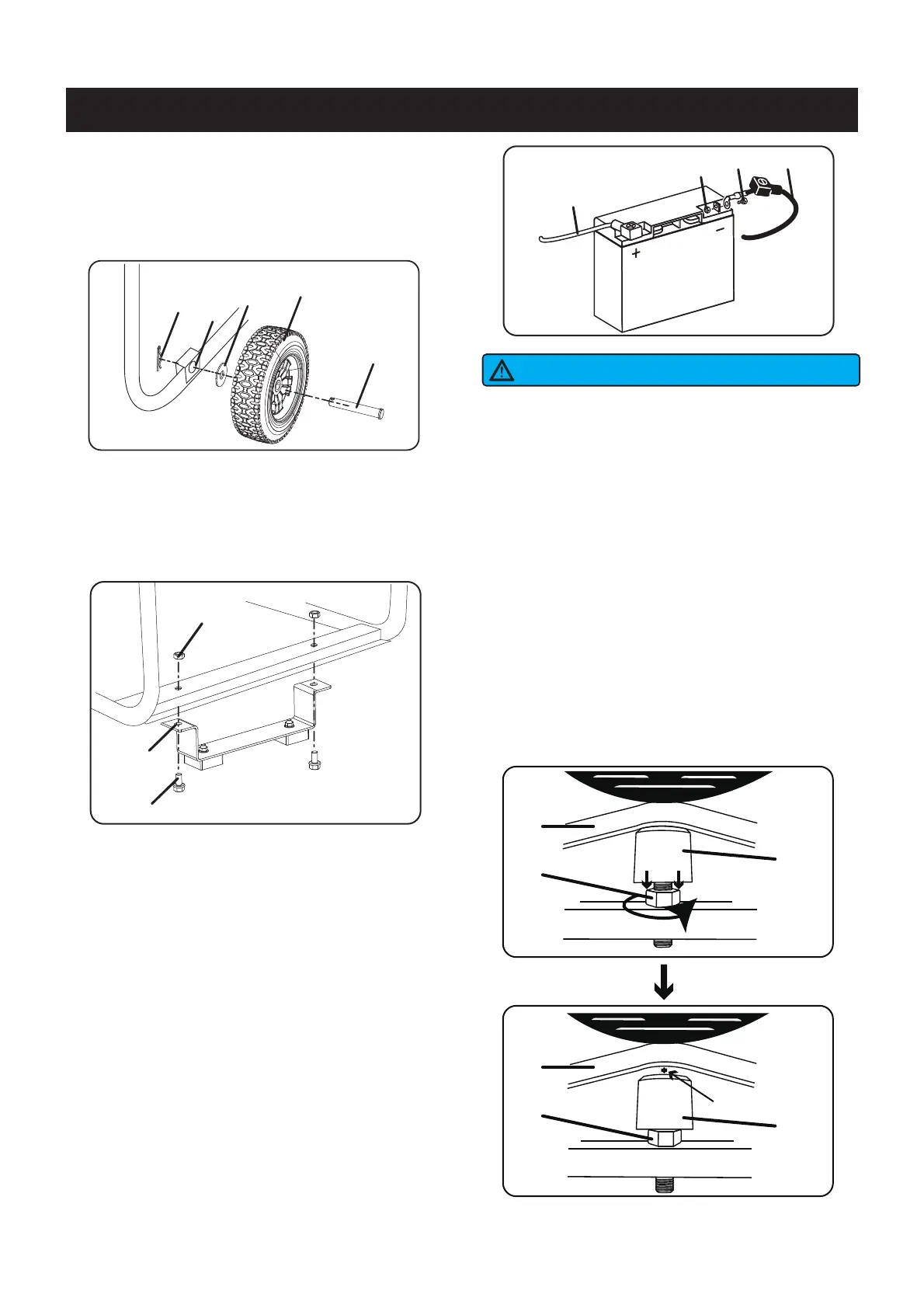
3 - Slide axle pin (A) through the wheel (B), flat
washer (C) and generator frame axles hole (D).
4 - Secure everything with cotter pin (E). Repeat on
opposite side.
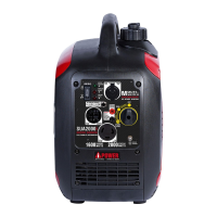
Install the Support Leg
5 - Insert bolts (F) throught the support leg (G) and
holes on the generator frame as shown.
6 - Tighten bolts (F) and nuts (H) to the frame.
M
K
L
M
K
L
G
F
H
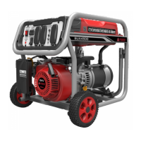
Battery Cable Connection
A
B
C
D
E
The generator is equipped with a battery charging
feauture. Once the engine is running,a small charge
will slowly recharge the battery.
If you do not plan to use the generator for a long
period of time,we recommend to DISCONNECT the
battery plugs A and B to protect the battery from
losing charge,You may also to use a battery
float charger (not included) to maintain battery
charge.
NOTICE
A
BD
C
NOTE: The generator comes equipped with the
positive cable A (with red boot) already attached.
1. Verify the positive (+) battery cable A with red
boot is securely tightened to the positive (+)
battery post. Make sure boot is over battery post.
2. Remove bolt B (M6x12) and nut C from battery
negative (-) post.
3. Locate negative (-) battery cable D with black boot
and attach to the negative (-) battery post. Tight the
cable with bolt B and nut C. Cover the post with
black boot.