b. The ow switch veries that water is owing during a feed
cycle, and sends the controller instrucons to deacvate
the feed if water is not owing.
c. Operaon of this controller without a funconing ow-
switch will void the NSF Cercaon. Rounely check that
the ow-switch is funconing by closing the le valve on
the boom of the ow-cell (ow light should turn o).
3. pH and ORP Sensors
a. pH Sensor – standard (Use only IPS Controllers part # SXPH
to maintain NSF Cercaon)
b. ORP Planum Sensor – standard (Use only IPS Controllers
part # SXORP to maintain NSF Cercaon)
c. ORP Gold Sensor - for use with Salt Chlorine systems
(Use only IPS Controllers part # SXORP-G to maintain NSF
Cercaon)
4. Fings – for tapping installaon of ow cell input/output
5. In-line Filter – installed prior to ow cell to protect ow switch
and sensors
6. Tubing – 25 feet of 3/8” for providing ltered water to and from
the ow cell
7. Mounng Board – ABS plasc with mounng holes and
stainless hardware (16” x 12” standard, 24” x 19” oponal)
8. Chemical Feeders – peristalc pumps for pH and ORP control
(purchased separately)
5
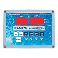
M720 pH/ORP Controller Owner’s Manual