Do you have a question about the IPS Controllers M820 and is the answer not in the manual?
Explains pH and ORP, water balance, and factors affecting water quality.
Covers electrical safety, user supervision, cord handling, installation clearances, and general warnings.
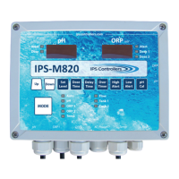
Details the controller's automatic monitoring, user interface, digital readouts, and function buttons.
Describes the flow cell, flow switch, pH/ORP sensors, fittings, filter, tubing, mounting board, and temp sensor.
Lists enclosure dimensions, electrical input/output, set levels, dose/delay times, alerts, readout, and alarm types.
Explains the meaning of various LEDs and digital displays on the pH and ORP sections of the controller.
Details the function of the Mode button, Up/Down arrows for parameter adjustments, and specific LEDs.
Lists the electrical connections for pH output, ORP1/ORP2 output, AC power, flow, and tank level switches.
Details power input requirements, GFCI needs, and the function of dip switches for configuration.
Instructions for turning off equipment, relieving pressure, and listing necessary tools for installation.
Guides on selecting an appropriate installation location and securely mounting the controller board.
Details plumbing connections, flow cell setup, and pH/ORP sensor installation.
Steps for drilling a hole and installing the optional temperature sensor.
Guides on connecting feeder devices, power, sensors, and optional Salt Chlorine Generator (SCG).
Details how to convert the controller from using a power cord to a permanent hardwired connection.
Explains the controller's basic function and the initial startup process, including flow verification and manual balancing.
Details the steps to safely turn off the M820 controller, including standby modes and display indicators.
Describes the normal operational mode and the pH standby mode for adjustments.
Details how to adjust Set Level and Dose Time within the pH standby mode.
Details adjustments for Delay Time, Over Timer, High Alert, Low Alert, and pH Calibration.
Explains the ORP1 standby mode and how to adjust its Set Level.
Details adjustments for Dose Time, Delay Time, Over Timer, High Alert, and Low Alert for ORP1.
Explains the ORP2 standby mode and how to adjust its Set Level and Dose Time.
Details adjustments for Dose Time, Delay Time, and Over Timer for ORP2.
Describes how to display and calibrate temperature readings and explains flow monitoring features.
Explains how the controller handles flow monitoring, including the flow switch and pre-mounted boards.
Details how to lock/unlock buttons to prevent unauthorized changes and force manual dosing.
Instructions on how to return the controller to its original factory settings and enter test mode.
Procedures for winterizing the controller and sensors during extended shutdowns or cold climates.
Guidelines for cleaning pH and ORP sensor tips to ensure accurate readings.
Steps for verifying the functionality and accuracy of the pH and ORP sensors.
Addresses common problems like pH being too low or too high, and potential causes.
Discusses issues with chlorine/bromine levels being too low, including pH adjustment and ORP set level checks.
Covers problems with high chlorine/bromine levels and troubleshooting for display/LED issues.
Addresses feeder operation problems and troubleshooting for the flow LED being off.
Addresses issues where feeders are not operating, including no flow, inadequate flow, or blown output fuses.
Guides on troubleshooting why the flow LED is not illuminated, checking valves, pressure, and connections.
Details the 5-year warranty for the controller and 1-year for other components.
Outlines exclusions from the warranty and procedures for submitting warranty claims.
| Model | M820 |
|---|---|
| Number of Channels | 8 |
| Category | Controller |
| Supported Interfaces | Ethernet |
| Voltage Range | 24V DC |
| Power Supply | 24V DC |