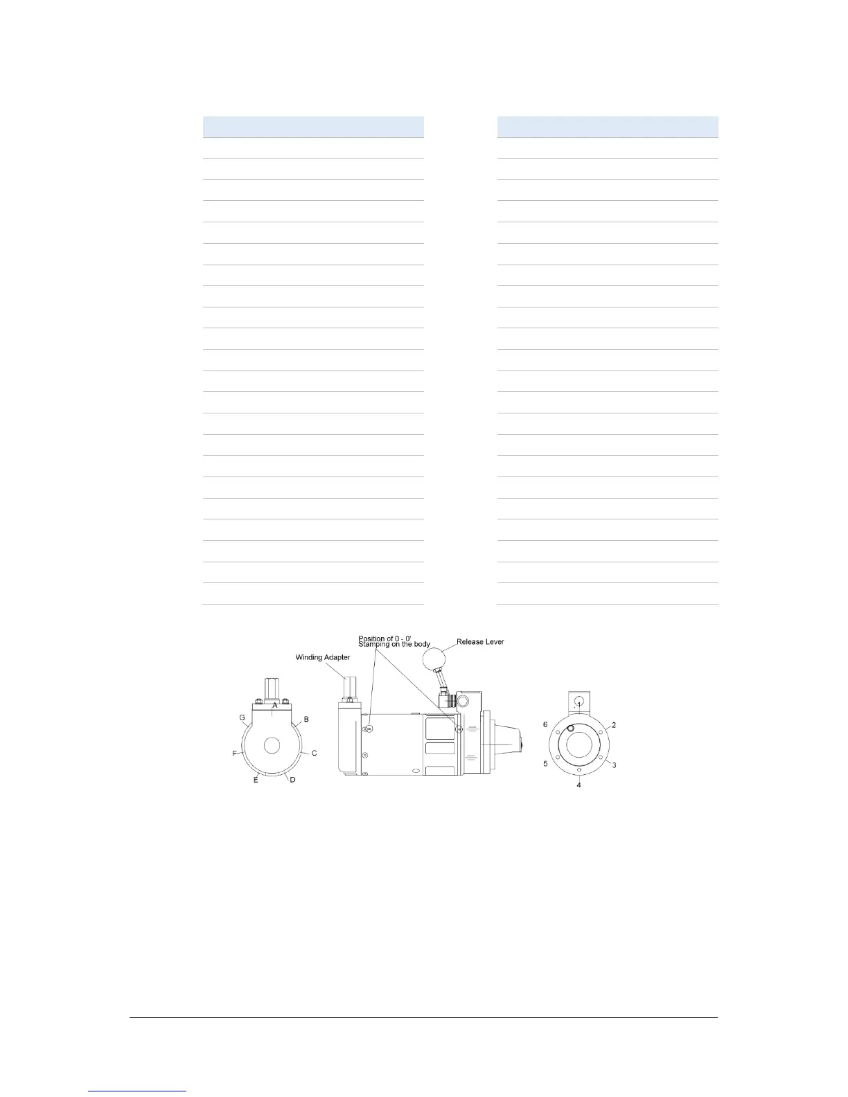
EasyManuals Logo

IPU Spring Starter User Manual

IPU Spring Starter
24 pages
To Next Page IconTo Next Page
To Previous Page IconTo Previous Page
Page #18 background imageLoading...
Page #18 background image
P a g e | 18
Position Code Table
Code
Angle '+'
Code
Angle '-'
1A
0
1A
0
2B
8.6
6G
8.6
3C
17.1
5F
17.1
4D
25.7
4E
25.7
5E
34.2
3D
34.2
6F
42.9
2C
42.9
1G
51.4
1B
51.4
2A
60
6A
60
3B
68.6
5G
68.6
4C
77.1
4F
77.1
5D
85.7
3E
85.7
6E
94.2
2D
94.2
1F
102.9
1C
102.9
2G
111.6
6B
111.6
3A
120
5A
120
4B
128.6
4G
128.6
5C
137.1
3F
137.1
6D
145.7
2E
145.7
1E
154.2
1D
154.2
2F
162.9
6C
162.9
3G
171.4
5B
171.4
4A
180
4A
180
Fig 4 Fig 5 Fig 6
Note: The six through holes on the front housing are designated by numbers 1 to 6 clockwise,
looking from the rear of the housing (Fig 6).
The seven radial tapped holes on the rear housing are designated by letters A to G clockwise,
looking from the rear of the housing (Fig 4).
On the starter body, only two of the holes at either end are in line. These are marked with ‘O’ next
to each hole (Fig 5).

Questions and Answers:

Question and Answer IconNeed help?

Do you have a question about the IPU Spring Starter and is the answer not in the manual?

IPU Spring Starter Specifications

General IconGeneral
BrandIPU
ModelSpring Starter
CategoryController
LanguageEnglish