18
Laser Command Signals
During laser bench testing, it is recommended that command signals be generated from an
Iradion Laser Controller or properly programed pulse generator. These units can provide the
tickle pulse and drive signals needed to test and operate the laser properly. Alternatively, most
motion control software packages are designed to provide the proper pulse protocol.
The Modulation pins on both the “D” connector, pins 3 (low) and 4 (high) and the RJ-45, pins
1 (high) and 6 (low) are designed to allow either floating or grounded input modes.
Both the High and Low pins should be used in either case. A software setting made
through the RS232 interface will either ground Modulation Low or leave it floating. Factory
setting is set to ground Modulation Low.
It is possible to use the Modulation High pin only if the Modulation Low pin is grounded by
software settings or by a physical wire; however, depending on the ground integrity of the host
system and level of ground noise this may not be the best solution.
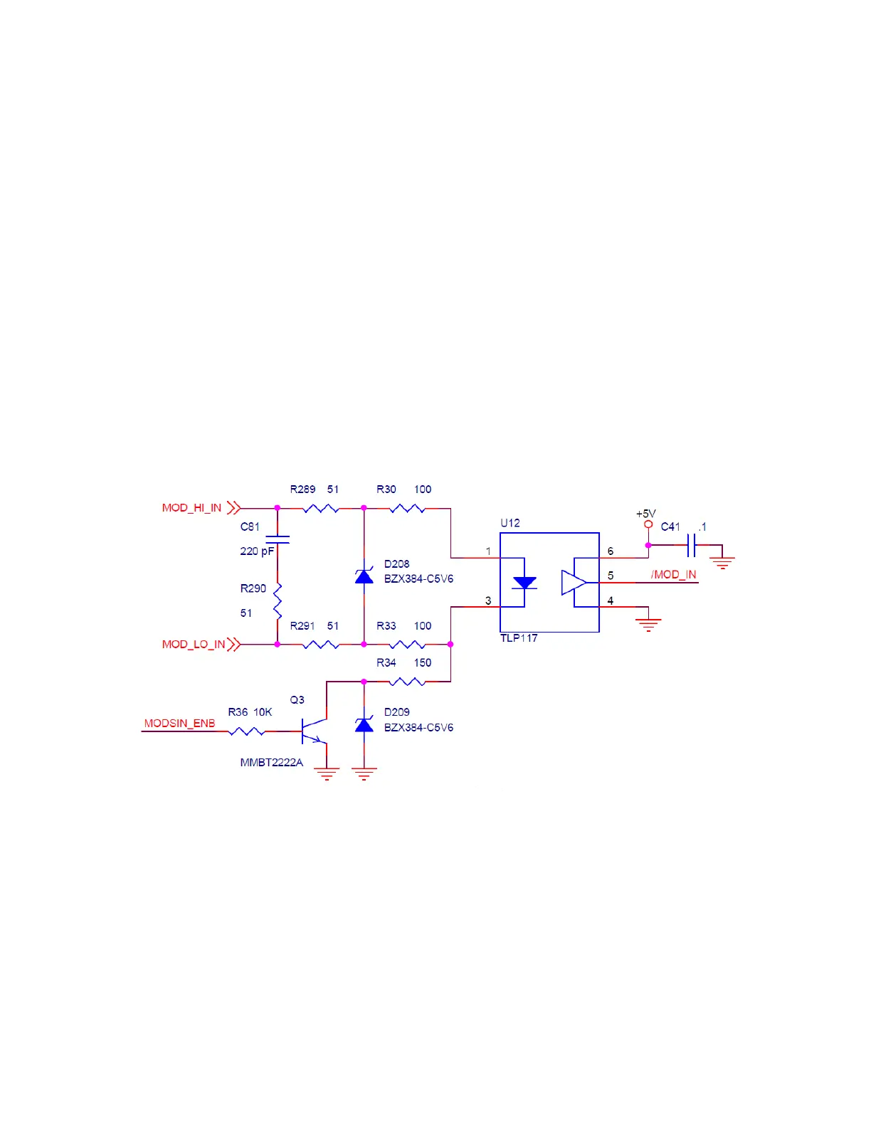
The diagram below shows the circuit of the modulation input interface: