19
System Test
The operation of the laser is possible after the above connections are completed. To test the
laser, apply power and the tickle command signal. If the software settings require a key switch,
toggle it off and on. After about 6 seconds, the system will be armed.
The interlock connections must be closed to operate the system.
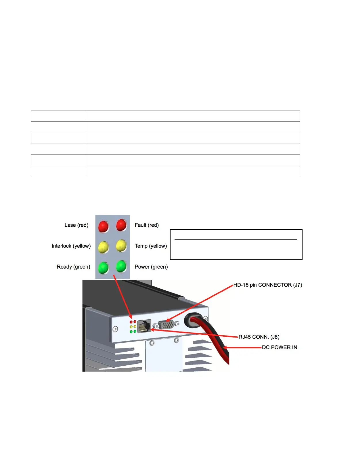
Fault conditions can be detected by viewing the LED indicators on the rear of the laser. The
signals monitored with LEDs are:
Lights up when the laser controller is ready for operation.
Lights up when the RFPA is getting too hot. Faults at Temp limit.
Lights up when the controller is in a Fault state.
Lights up whenever signals are delivered to the RFPA FET bias.
Lights up whenever DC power is applied.
Lights up when the interlock switch is closed.
Laser Indicator Lights
Cooling Temp Lights Faults
Air 55˚C 60˚C
Water 35˚C 40˚C