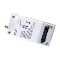
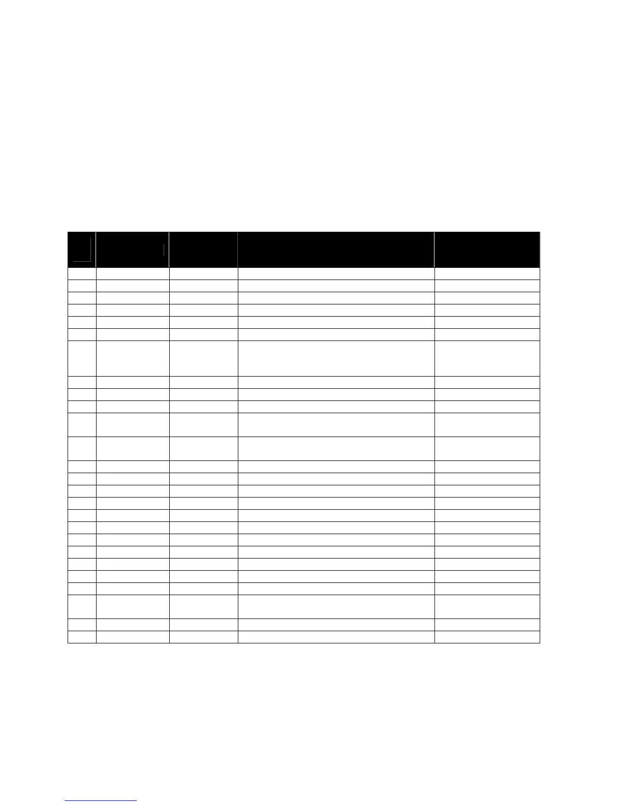
5.1.2 Connector Pin Allocation
The user connector is a 2 row 26-way latching header. Individual pin assignments are shown in Table 7.
Multiple supply grounds are provided and all supply and supply grounds (pins 1-6) are required to be
connected to the power supply in order to limit the current on any one pin. The three Supply Returns (pins
4, 5 & 6) are tied together at the connector as well as the three Supply pins (pins 1, 2 & 3.) Multiple signal
grounds are provided to reduce cross-talk. The signal grounds on pins 10,13, 20 & 23 are all tied together
at the connector and can be joined with any of the signal wires e.g. RS232, Network Available etc.
However each signal requires its own signal ground in order to limit current on any one pin.
Table 7: Multi Interface Connector Pin Allocation
Pin
No.
Signal Name
Signal
direction
(WRT 9601)
Signal function Signal level
1 EXT_PWR Input Supply +5 V +/- 0.5 V
2 EXT_PWR Input Supply +5 V +/- 0.5 V
3 EXT_PWR Input Supply +5 V +/- 0.5 V
4 EXT_GND Supply return 0 V
5 EXT_GND Supply return 0 V
6 EXT_GND Supply return 0 V
7 ON/OFF Input On/Off control input
On: 2.0V to Vsupply
Off: 0V to 0.5V
I = 120 A max
8 Reserved
9 Reserved
10 SIG_GND Signal ground 0V
11 DF_S_TX Input
Data port, serial data into 9601 SBD
Transceiver
RS-232
12 DF_S_RX Output
Data port, serial data from 9601 SBD
Transceiver
RS-232
13 SIG_GND Signal ground 0V
14 DF_ DCD Output Data port, Data Carrier Detect RS-232
15 DF_ DSR Output Data port, Data Set Ready RS-232
16 DF_ CTS Output Data port, Clear-to-Send RS-232
17 DF_RI Output Data port, Ring Indicator RS-232
18 DF_ RTS Input Data port, Request-to-Send RS-232
19 DF_ DTR Input Data port, Data Terminal Ready RS-232
20 SIG_GND Signal ground 0V
21 Reserved
22 Reserved
23 SIG_GND Signal ground 0V
24
NETWORK_
AVAILABLE
Output Set to logic 1 when network is visible 2.9 V CMOS
25 Reserved
26 Reserved
Figure 9 provides a reference for the pin designation. Note that this designation is when looking into the
multi-interface connector from above. It is not to scale and not representative of the actual connector
mechanical layout.