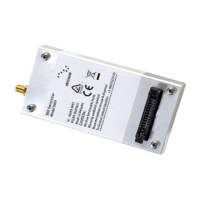
01 03
02
Connector notch
26
2501 03
02
Connector notch
26
25
Figure 9: Multi-Interface Connector Pin Number Designation
Notes for figure 9:
1. View looking into connector from above
2. Numbers indicate pin designations
3. Not to scale, for illustrative purposes only
4. Note location of connector notch
5. Connector notch faces towards opposite end to the antenna connector as shown in Figure 10
6. On the physical connector Pin 1 is indicated by an arrow mark
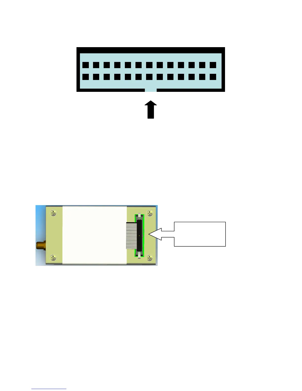
Figure 10: Multi Interface Connector Notch Location
5.2 DC Power Interface
The DC power interface is comprised of the DC power inputs and a control signal as summarized in Table
7. The three +5V Inputs and three 0V supply returns are used to supply DC power to the 9601 and ensure
that enough current can be drawn across the connector without the 9601 malfunctioning during transmit
due to lack of current supply. Note that all six pins should be connected.
The DC power supply requirements for the 9601 are summarized in Table 8 below. Note that these
requirements apply to DC power measured at the 9601 multi-interface connector input and not at the
output of the power supply. Long power supply cables can cause a voltage drop sufficient to cause the
voltage to be out of specification at the physical power supply input to the 9601.
Notch on
side