IPU 40108
Page 10 of 29
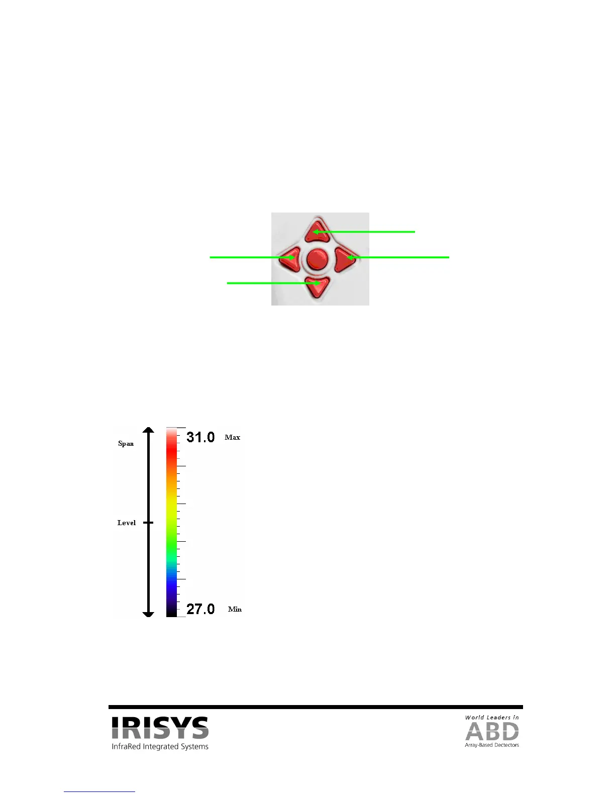
3.4.5 Directional Buttons
The directional buttons (up, down. left & right – see Figure 13) are used for three different functions.
1. If hot button 3 is set to either SP+ or SPX, the directional buttons control the position of the
selected temperature cursor. (Selection displayed above hot button 3).
2. If hot button 3 is set to L-S, “up” and “down” control the manual mode’s image temperature level,
and “left” and “right” control the temperature span. See Section 3.4.6.1 for details. If hot button 3
is set to B-C, “up” and “down” control the auto mode’s target image thermal brightness, and “left”
and “right” control the target thermal contrast. See Section 3.4.9.1 for details.
3. If the menu is displayed, the directional buttons control the movement of the highlighted cursor and
adjustment of the highlighted option (see Section 3.4.7).
Figure 13: Directional Buttons
3.4.6 Image Adjustment
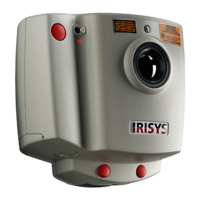
3.4.6.1 Level and Span Definitions
When hot button 4 is set to manual the IRI 4010’s image settings can be manually controlled by adjusting the
level and span. When hot button 3 shows L-S, the “right” and “left” buttons respectively will increase and
decrease the span of the image (4˚C in the example in Figure 14). The “up” and “down” buttons will increase
and decrease the thermal level of the image (29˚C in the example in Figure 14).
Figure 14: Level and Span
The IRI 4010’s image settings are fully automatic when hot button 4 is set to auto. The auto mode
automatically adjusts the level and span to display a presentable image.
Level = (Max + Min)/2 = 29˚C
Span = Max – Min = 4˚C
Down
Up