C.P. SENTINEL AUTOMATIC TYPE CATHODIC PROTECTION RECTIFIER MANUAL
INTEGRATED RECTIFIER TECHNOLOGIES, INC.
Doc #: APC0010
Rev. 3.0, November, 2004
Page 17 of 22
A NOTE ABOUT POTENTIAL READINGS!!
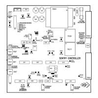
The SENTRY Controller is designed to provide IR-Free potential readings for control and
for display to the Potential Meter. This reading will differ from the measured Structure–
Reference Electrode inputs into the rectifier by the IR-Drop error. (Refer to description on
Page 13) The “Actual” potential from the SENTRY Controller will only correspond to the
measured Structure–Reference Electrode inputs into the rectifier with no current flowing;
i.e.: at no load. On rectifiers equipped with efficiency filters, true IR-Free operation cannot
be attained. The “Actual” potential will equate to the Structure–Reference Electrode
potential with minimal IR-Free error.
potential control “Set” level cannot be initially attained due to the polarization time of the
Structure, the rectifier will ramp up the DC output to either the Voltage set point (Voltage Limit;
Red LED illuminated) or the Current set point (Current Limit; Green LED illuminated). Once the
potential control “Set” level is attained, the SENTRY Controller will automatically revert into
Potential Mode and maintain the Structure to Reference Electrode potential at the preset level.
The Yellow LED will then be illuminated.
Rectifiers equipped with MANUAL MODE Option: Adjustment of rectifiers equipped with this
option requires the “Automatic-Manual” selector switch be switched to the “Manual” position.
Start the rectifier with the Coarse & Fine taps set to their lowest level (Coarse “A” – Fine “1”).
Observe and record if necessary the rectifier output currents and voltage levels, and the
polarization level of the Structure being protected. Incrementally, increase the transformer tap
settings until either target current or polarization levels are attained. The SENTRY Controller is
NOT required for manual mode, and may be removed for repair if it is not functioning correctly.
After the structure potential readings have been taken and prior to leaving the site, it is
recommended that the DC output connections to the rectifier be rechecked to ensure a secure
connection. It is also beneficial to recheck the rectifier to ensure that all air inlet and outlet venting
on the enclosure is not obstructed in any manner. The rectifier O&M manual should be securely
set in it’s holder (for small rectifiers without a manual holder, it is recommended that the manual
be kept with the main operator or in the control room of the closest station). Also verify that all
holes within the enclosure (other than the venting screens) are suitably plugged (such as unused
conduit knockouts). For rectifier units with “OFF-ON” meter switches, ensure that the switch is in
the “OFF” position prior to leaving the site.
APPLICATION NOTES:
1. Remember, the C.P. SENTINEL AQUA-LINE rectifiers are equipped with “Loss-of-
Reference” shutdown feature. The rectifier “REFERENCE SELECT” switch must be
set to sense an active and functional Reference Cell input or no output will occur from
the unit. Alternately, jumper the “REF. CELL” inputs on the front of the rectifier panel
to obtain a current output. A “Loss-of-Reference” shutdown will be evident by the
digital Potential Meter reading overload; first digit a “1” followed by remaining digits
blank.
2. To function in current mode up to rated current, the output of the rectifier cannot be
limited by either the “VOLTAGE SET” or the “POTENTIAL SET” potentiometers.
 Loading...