C.P. SENTINEL AUTOMATIC TYPE CATHODIC PROTECTION RECTIFIER MANUAL
INTEGRATED RECTIFIER TECHNOLOGIES, INC.
Doc #: APC0010
Rev. 3.0, November, 2004
Page 20 of 22
TROUBLESHOOTING
If a problem is found with the rectifier during the maintenance inspection or reported by the
local operator, the following troubleshooting procedure can be followed to determine the
cause.
The only way to effectively determine the cause of a failure in any piece of equipment is to
conduct a systematic analysis of the function and operation of the key components. For this
troubleshooting procedure, we shall review the possible faults that may occur starting from the
DC output and working back to the AC input.
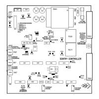
Please refer to the Rectifier Specifications Sheet, Electrical Schematic supplied with each
rectifier and to the SENTRY Controller layout on Page 9 of this manual for component
descriptions and test points. Common rectifier failures can be summarized and corrected as
follows:
A. NO RECTIFIER OUTPUT CURRENT: This fault may be caused by any one or more of the
following conditions:
No AC Present
: Check incoming utility supply for the presence of voltage and
that it is correct for the rating of the rectifier. Consult your electrician or
electrical utility to correct this problem.
Rectifier AC Breaker Tripped
: First: Do a visual inspection as described in the
Maintenance & Adjustment section of this manual. Secondly, attempt to reset
the breaker and observe rectifier output. If the rectifier fails to function correctly,
continue with this troubleshooting procedure.
Blown Fuse
: Check all rectifier fuses, including the control fuse located on the
SENTRY Controller circuit board. Replace as required with the identical type,
size and rating as supplied. One spare for each fuse used in the unit is supplied
with each rectifier.
Check Interrupt Circuit
: It is possible for field attached external interrupter to
hold the output “Off”. Refer to Page 11, Section “C” and Page 15 “External
Interrupt Terminal Block” and correct any possible interrupter setting errors.
Improper Settings
: Review the settings on the SENTRY Controller for Voltage,
Current and Potential (if applicable). Any one of these potentiometers set to
“zero” will result in no rectifier output. Review “Controls” section of this manual
on Page 10, and correct any setting errors.
SENTRY Controller Failure
: Check for the board status LED’s. “Power ON”
LED is illuminated continually when the board is powered and the on-board
microprocessor is functioning. One of the Mode LED’s will function if any one of
the rectifier output modes is being controlled. Due to board complexity, replace
defective controller with a known working controller.
CAUTION!!
Please be advised that hazardous voltages are present within the rectifier unit even with
the rectifier AC input circuit breaker in the “OFF” position. Extreme care should be
observed when taking measurements on the front of the instrument panel or the side AC
input panel. Only qualified electronic or electrical technicians should attempt internal
troubleshooting of the rectifier. The fused AC disconnect should be set to the “OFF”
position prior to any internal rectifier maintenance or repair.