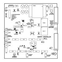
C.P. SENTINEL AUTOMATIC TYPE CATHODIC PROTECTION RECTIFIER MANUAL
INTEGRATED RECTIFIER TECHNOLOGIES, INC.
Doc #: APC0010
Rev. 3.0, November, 2004
Page 12 of 22
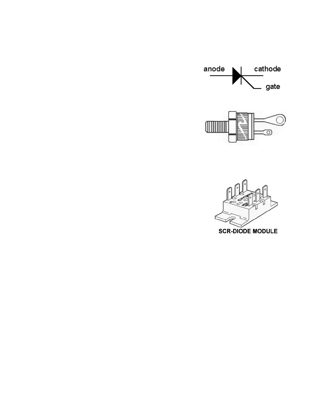
THE SILICON CONTROLLED RECTIFIER (SCR)
Automatically controlled rectifiers utilize phase control of the
supplied 50 or 60 Hertz AC voltage using a solid-state device
called a Silicon Controlled Rectifier (SCR). This device is
similar to a conventional diode, but is equipped with an extra
terminal for control called the GATE. Although akin to a diode,
this device has unique properties of being able to block
conduction of current when the device is forward biased until
an appropriate signal is applied to the Gate terminal. Once the
appropriate gate signal is applied, the SCR remains in
conduction while forward biased, or until the current trough the
device goes to almost zero.
The control of the rectifier DC output is accomplished by “gating
on” the SCR at the point in the AC waveform necessary to
produce the desired output. This output can be the regulated
DC Voltage, the DC Current, the Structure to Reference
Electrode Potential or a combination of the three modes of
control. A minimum of two SCR’s are required to achieve full control over the AC waveform. The
two SCR’s are configured with two diodes into a full-wave bridge configuration.
Often SCR’s and diodes are combined into full-wave controlled
rectification modules. Typically the modules used are comprised
of two SCR’s and two diodes with the cathodes of the 2 SCR’s
connected to the module Positive (+) terminal. SCR-Diode
modules are then mounted to a suitably sized heatsink for
cooling.